| 基于STM32配置PWM的输出和相关GPIO口的配置(有关重映像问题解答) | 您所在的位置:网站首页 › 蜂鸣器哪个引脚接地 › 基于STM32配置PWM的输出和相关GPIO口的配置(有关重映像问题解答) |
基于STM32配置PWM的输出和相关GPIO口的配置(有关重映像问题解答)
|
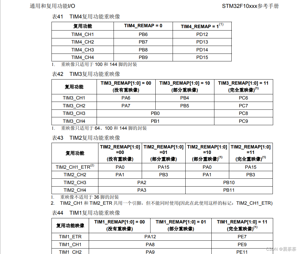
使用STM32定时器进行PWM的配置有以下几个步骤,以下是参考例差可以作为历程参考。 /****************************************************************************************************************************** *使用PWM来实现对电机的控制,实现开环的速度控制 * *使用四个直流电机 motor1: motor2: * motor3: motor4: * cnt = 0 对应占空比0 TIM3:(部分重映像) CH1:PB4 CH2:PB5 CH3:PB0 CH4:PB1 TIM4: CH1:PB6 CH2:PB7 CH3:PB8 CH4:PB9 *******************************************************************************************************************************/ void TIM_PWM_Init(void) { //设置变量 GPIO_InitTypeDef GPIO_InitStructure; TIM_TimeBaseInitTypeDef TIM_TimeBaseStructure; TIM_OCInitTypeDef TIM_OCInitStructure; //使能时钟 RCC_APB1PeriphClockCmd( RCC_APB1Periph_TIM3 | RCC_APB1Periph_TIM4 , ENABLE); RCC_APB2PeriphClockCmd( RCC_APB2Periph_GPIOB | RCC_APB2Periph_AFIO, ENABLE); GPIO_PinRemapConfig( GPIO_PartialRemap_TIM3 , ENABLE);//使定时器TIM4进行部分重映像操作 //GPIO_PinRemapConfig(GPIO_Remap_TIM4,ENABLE); TIM_TimeBaseStructure.TIM_Period = 899; TIM_TimeBaseStructure.TIM_Prescaler = 0; TIM_TimeBaseStructure.TIM_CounterMode = TIM_CounterMode_Up; TIM_TimeBaseStructure.TIM_ClockDivision = 0; TIM_TimeBaseInit(TIM3 , &TIM_TimeBaseStructure); TIM_TimeBaseInit(TIM4 , &TIM_TimeBaseStructure); //端口复用 GPIO_InitStructure.GPIO_Pin = GPIO_Pin_0 | GPIO_Pin_1 | GPIO_Pin_4 | GPIO_Pin_5 | GPIO_Pin_6 | GPIO_Pin_7 | GPIO_Pin_8 | GPIO_Pin_9 ; GPIO_InitStructure.GPIO_Speed = GPIO_Speed_50MHz; GPIO_InitStructure.GPIO_Mode = GPIO_Mode_AF_PP; GPIO_Init(GPIOB, &GPIO_InitStructure); //PB4:TIM3_CH1 TIM_OCInitStructure.TIM_OCMode = TIM_OCMode_PWM1; TIM_OCInitStructure.TIM_OutputState = TIM_OutputState_Enable; TIM_OCInitStructure.TIM_OCPolarity = TIM_OCPolarity_High; TIM_OCInitStructure.TIM_Pulse = 0; TIM_OC1Init(TIM3 , &TIM_OCInitStructure); TIM_OC1PreloadConfig(TIM3 , TIM_OCPreload_Enable); //PB5:TIM3_CH2 TIM_OCInitStructure.TIM_OCMode = TIM_OCMode_PWM1; TIM_OCInitStructure.TIM_OutputState = TIM_OutputState_Enable; TIM_OCInitStructure.TIM_OCPolarity = TIM_OCPolarity_High; TIM_OCInitStructure.TIM_Pulse = 450; TIM_OC2Init(TIM3 , &TIM_OCInitStructure); TIM_OC2PreloadConfig(TIM3 , TIM_OCPreload_Enable); //PB0:TIM3_CH3 TIM_OCInitStructure.TIM_OCMode = TIM_OCMode_PWM1; TIM_OCInitStructure.TIM_OutputState = TIM_OutputState_Enable; TIM_OCInitStructure.TIM_OCPolarity = TIM_OCPolarity_High; TIM_OCInitStructure.TIM_Pulse = 0; TIM_OC3Init(TIM3 , &TIM_OCInitStructure); TIM_OC3PreloadConfig(TIM3 , TIM_OCPreload_Enable); //PB1:TIM3_CH4 TIM_OCInitStructure.TIM_OCMode = TIM_OCMode_PWM1; TIM_OCInitStructure.TIM_OutputState = TIM_OutputState_Enable; TIM_OCInitStructure.TIM_OCPolarity = TIM_OCPolarity_High; TIM_OCInitStructure.TIM_Pulse = 0; TIM_OC4Init(TIM3 , &TIM_OCInitStructure); TIM_OC4PreloadConfig(TIM3 , TIM_OCPreload_Enable); // //PB6:TIM4_CH1 TIM_OCInitStructure.TIM_OCMode = TIM_OCMode_PWM1; TIM_OCInitStructure.TIM_OutputState = TIM_OutputState_Enable; TIM_OCInitStructure.TIM_OCPolarity = TIM_OCPolarity_High; TIM_OCInitStructure.TIM_Pulse = 900; TIM_OC1Init(TIM4 , &TIM_OCInitStructure); TIM_OC1PreloadConfig(TIM4 , TIM_OCPreload_Enable); //PB7:TIM4_CH2 TIM_OCInitStructure.TIM_OCMode = TIM_OCMode_PWM1; TIM_OCInitStructure.TIM_OutputState = TIM_OutputState_Enable; TIM_OCInitStructure.TIM_OCPolarity = TIM_OCPolarity_High; TIM_OCInitStructure.TIM_Pulse = 900; TIM_OC2Init(TIM4 , &TIM_OCInitStructure); TIM_OC2PreloadConfig(TIM4 , TIM_OCPreload_Enable); //PB8:TIM4_CH3 TIM_OCInitStructure.TIM_OCMode = TIM_OCMode_PWM1; TIM_OCInitStructure.TIM_OutputState = TIM_OutputState_Enable; TIM_OCInitStructure.TIM_OCPolarity = TIM_OCPolarity_High; TIM_OCInitStructure.TIM_Pulse = 0; TIM_OC3Init(TIM4 , &TIM_OCInitStructure); TIM_OC3PreloadConfig(TIM4 , TIM_OCPreload_Enable); //PB9:TIM4_CH4 TIM_OCInitStructure.TIM_OCMode = TIM_OCMode_PWM1; TIM_OCInitStructure.TIM_OutputState = TIM_OutputState_Enable; TIM_OCInitStructure.TIM_OCPolarity = TIM_OCPolarity_High; TIM_OCInitStructure.TIM_Pulse = 900; TIM_OC4Init(TIM4 , &TIM_OCInitStructure); TIM_OC4PreloadConfig(TIM4 , TIM_OCPreload_Enable); TIM_Cmd(TIM3, ENABLE); TIM_Cmd(TIM4, ENABLE); }在上述PWM初始化函数中使用定时器TIM3和TIM4来输出PWM波,其中为了更好的应用IO口的布局等等TIM3进行了部分重映像的操作,这意味着部分引脚可以使用重映像的操作使之拥有另外的功能,即让TIM4本来该复用的引脚重映像到了其他引脚上。这个时候我们就需要查找相关的参考手册来对比引脚关系。如我使用的STM32F103。
通过表格我们就可以知道我想要使用PB4和PB5作为PWM的输出引脚,所以对TIM3使用了部分重映像的功能,实现这个功能的代码是: GPIO_PinRemapConfig( GPIO_PartialRemap_TIM3 , ENABLE);//使定时器TIM3进行部分重映像操作这里有一个值得注意的地方,若是其他的功能引脚需要复用IO口,同样也是需要相同的方法来对该外设进行部分重映像或完全重映像(若是没有重映象则不需要),而需要重映像对象则可以在库函数中找到。如我需要使用PD8和PD9作为USART3的TXD和RXD引脚则需要完全重映像USART3: RCC_APB1PeriphClockCmd( RCC_APB1Periph_USART3, ENABLE ); /* 使能USART1,GPIOA时钟 */ GPIO_PinRemapConfig(GPIO_FullRemap_USART3,ENABLE); //完全重映像USART3,使用PD8和PD9作为USART3的TXD和RXD引脚除了重映像的问题其余就是以下几个步骤: (1)使能时钟 (2)配置GPIO口 pin、speed、mode等,其中mode需选择为GPIO_Mode_AF_PP复用输出。 (3)配置基本的定时器参数, typedef struct { uint16_t TIM_Prescaler; /*!< Specifies the prescaler value used to divide the TIM clock. This parameter can be a number between 0x0000 and 0xFFFF */ uint16_t TIM_CounterMode; /*!< Specifies the counter mode. This parameter can be a value of @ref TIM_Counter_Mode */ uint16_t TIM_Period; /*!< Specifies the period value to be loaded into the active Auto-Reload Register at the next update event. This parameter must be a number between 0x0000 and 0xFFFF. */ uint16_t TIM_ClockDivision; /*!< Specifies the clock division. This parameter can be a value of @ref TIM_Clock_Division_CKD */ uint8_t TIM_RepetitionCounter; /*!< Specifies the repetition counter value. Each time the RCR downcounter reaches zero, an update event is generated and counting restarts from the RCR value (N). This means in PWM mode that (N+1) corresponds to: - the number of PWM periods in edge-aligned mode - the number of half PWM period in center-aligned mode This parameter must be a number between 0x00 and 0xFF. @note This parameter is valid only for TIM1 and TIM8. */ } TIM_TimeBaseInitTypeDef;TIM_Prescaler:定时器分频系数psc,对时钟频率进行分频; TIM_CounterMode:计数模式,向上计数或是向下计数 TIM_Period:时钟周期 TIM_ClockDivision:时钟分频。(设置为0即可) (4)配置定时器的输出参数: //PB4:TIM3_CH1 TIM3通道1 TIM_OCInitStructure.TIM_OCMode = TIM_OCMode_PWM1;//PWM1输出模式 TIM_OCInitStructure.TIM_OutputState = TIM_OutputState_Enable; TIM_OCInitStructure.TIM_OCPolarity = TIM_OCPolarity_High; TIM_OCInitStructure.TIM_Pulse = 0;//cnt捕获值,和占空比有关 TIM_OC1Init(TIM3 , &TIM_OCInitStructure); TIM_OC1PreloadConfig(TIM3 , TIM_OCPreload_Enable);PWM的占空比为n = pul/arr PWM的周期计算为 T = psc/72M(f103的时钟频率)*arr 如arr=1000,psc=7200,arr=1000则可计算PWM周期为T=7200/72000000*1000=0.1s f=1/T=10HZ (5)使能TIM定时器 TIM_Cmd(TIM3, ENABLE); TIM_Cmd(TIM4, ENABLE); TIM_Cmd(TIM2, ENABLE);这就是初始化PWM的整个流程,希望可以帮助到你。 |
【本文地址】