| STC16f40k128 使用VOFA+进行电机PID参数整定 | 您所在的位置:网站首页 › 如何调试智能小车模式 › STC16f40k128 使用VOFA+进行电机PID参数整定 |
STC16f40k128 使用VOFA+进行电机PID参数整定
|
文章目录
前言VOFA+简介必要工作配置STC16的UART模块VOFA+使用
前言
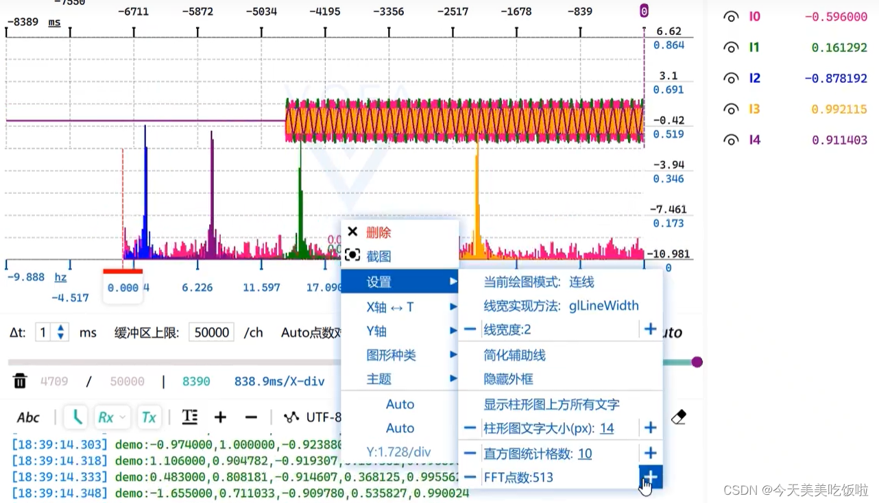
最近为了准备智能车比赛,参加相关培训,受学长推荐受用VOFA+上位机可视化波形,协助电机转速PID调整。 但是我这个芯片吧,STC16它不支持在线仿真,所以看关键变量的话就必须得借助串口来协助调试程序了。 VOFA+简介VOFA+是一个串口调试助手,但凭它简单的通信协议、数据可视化以及频域分析,三维打印等优点在众多串口调试助手中脱颖而出。 下面讲解一下如何使用keil对STC16进行开发时,将需要重点关注的变量打印到VOFA+上来,甚至对其可视化。 配置STC16的UART模块VOFA+本质上是一个串口,打印我们想要关注的数据就是需要STC16和串口之间的通信。STC16上有专门用于通信的模块UART(通用异步收发传输器),他的通信协议相较于其他的IIC,SPI,CAN等通信协议都简单得多,UART也更容易上手。 (UART 原理我就不讲了 直接贴代码吧) uart.c文件 文件中包含uart初始化函数以及通信字符传输函数,文件中已经对printf做了重定向,像c语言直接printf(“”)想要的数据就可以实现了 #include "stc16f.h" #include "stdio.h" #include "uart.h" #include "led.h" #include "pid.h" unsigned char TX1_Cnt; //发送计数 unsigned char RX1_Cnt; //接收计数 unsigned char TX2_Cnt; //发送计数 unsigned char RX2_Cnt; //接收计数 unsigned char TX3_Cnt; //发送计数 unsigned char RX3_Cnt; //接收计数 unsigned char TX4_Cnt; //发送计数 unsigned char RX4_Cnt; //接收计数 static uint8_t tempData[16] = {0,0,0,0,0,0,0,0,0,0,0x80,0x7F}; bit B_TX1_Busy; //发送忙标志 bit B_TX2_Busy; //发送忙标志 bit B_TX3_Busy; //发送忙标志 bit B_TX4_Busy; //发送忙标志 unsigned char xdata RX1_Buffer[UART1_BUF_LENGTH]; //接收缓冲 unsigned char xdata RX2_Buffer[UART2_BUF_LENGTH]; //接收缓冲 void Init_UART1(void) { TR1 = 0; AUXR &= ~0x01; //S1 BRT Use Timer1 AUXR |= (1 SBUF = *puts; B_TX1_Busy = 1; while(B_TX1_Busy); } } void UART1_int (void) interrupt 4 { LED_A_TG; if(RI) { RI = 0; RX1_Buffer[RX1_Cnt] = SBUF; if(++RX1_Cnt >= UART1_BUF_LENGTH) RX1_Cnt = 0; } if(TI) { TI = 0; B_TX1_Busy = 0; } } void UART1_SendData(char dat) { // ES = 0; //关串口中断 SBUF = dat; B_TX1_Busy = 1; while(B_TX1_Busy); //等待发送成功 // TI = 0; //清除发送中断标志 // ES = 1; //开串口中断 } void UART1_SendString(char *s) { while(*s)//检测字符串结束符 { UART1_SendData(*s++);//发送当前字符 } } //void Vofa_Graph() //{ // static float temp[2]; // // temp[0] = pid_Speed.ReferenceValue; // temp[1] = pid_Speed.ActualValue; memcpy(tempData, (uint8_t *)&temp, sizeof(temp)); // write((char*)temp,sizeof(float)*2); //} char putchar(char c) { UART1_SendData(c); return c; }uart.h文件 #ifndef _UART_H_ #define _UART_H_ #include "stc16f.h" #define BaudRate1 9600// #define BaudRate2 19200 #define BaudRate3 115200 #define BaudRate4 4800 #define BaudRate1Timer (65536 - MAIN_Fosc / BaudRate1 / 4) #define BaudRate2Timer (65536 - MAIN_Fosc / BaudRate2 / 4) #define BaudRate3Timer (65536 - MAIN_Fosc / BaudRate3 / 4) #define BaudRate4Timer (65536 - MAIN_Fosc / BaudRate4 / 4) #define UART1_BUF_LENGTH 128 #define UART2_BUF_LENGTH 128 #define UART3_BUF_LENGTH 128 #define UART4_BUF_LENGTH 128 void Init_UART1(void); void Init_UART2(void); void Init_UART3(void); void Init_UART4(void); void PrintString1(u8 *puts); void UART1_SendData(char dat); void UART1_SendString(char *s); void Vofa_Graph(void); #endif我这里使用Timer1作为UART1的波特率发生器。虽然STC16有很多UART,用一个就够了,而且Timer3Timer4用来捕获电机的编码器输入进行测速,Timer0做定时中断。 若需要修改波特率,需要在uart.h文件中修改BaudRate1宏定义即可。 VOFA+使用打开VOFA软件后,对VOFA进行配置 根据firewater的协议,打印你想要观察的数据 |
 就凭一个打印波形,屁颠屁颠就冲这软件来了。
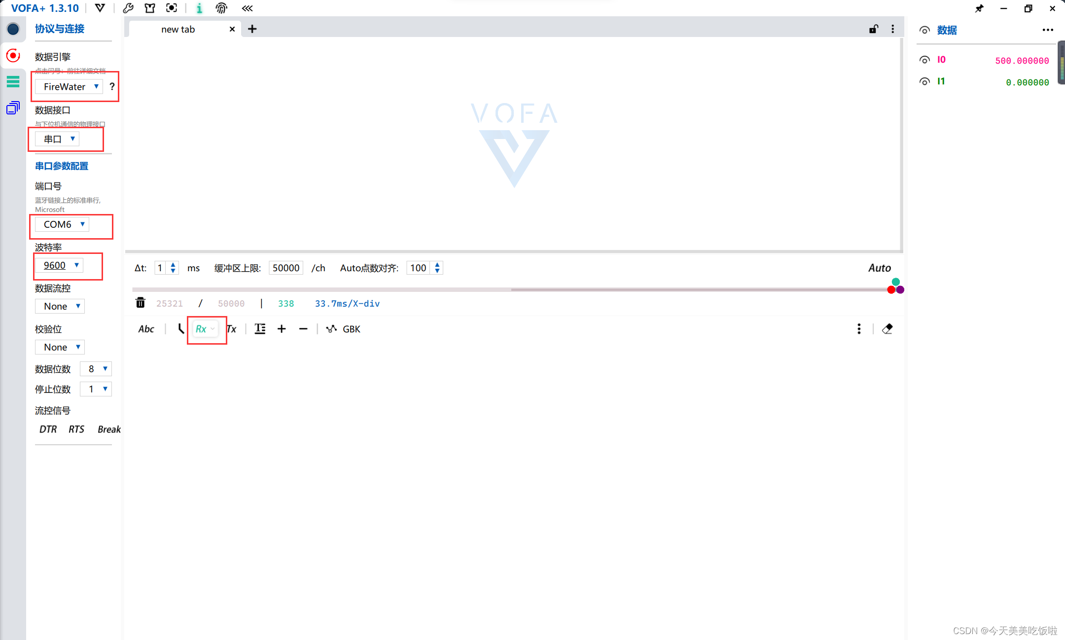 数据引擎选择firewater协议,这个协议可以简单打印数据波形。 数据接口选择stc16的com端口号,这个可以进设备管理器查看
 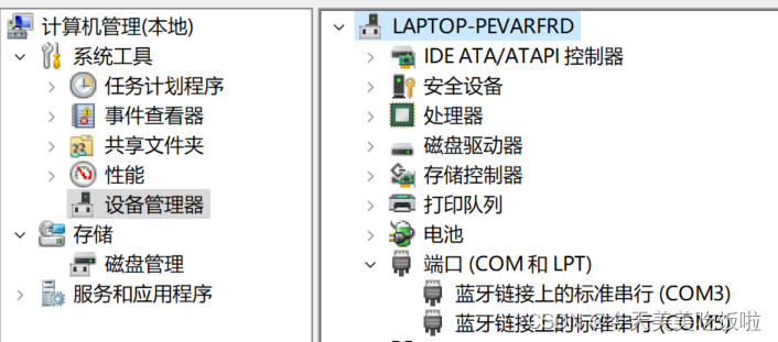 根据你配置的UART1的波特率,在VOFA上选择相同的波特率波特率一定要跟配置的一样,不然打印出来的就是乱码。
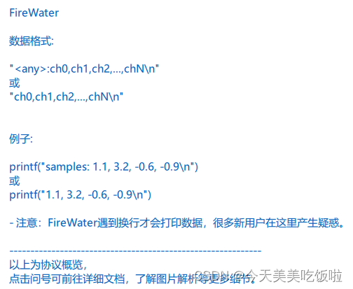 打印数据,printf函数我放在我的主函数里面的,整个文件贴上来了
【本文地址】