| 双目立体视觉三维重建 | 您所在的位置:网站首页 › 双目相机三维重建摄像机标定 › 双目立体视觉三维重建 |
双目立体视觉三维重建
|
Overview
欢迎访问 持续更新:https://cgabc.xyz/posts/aa4d53ac/ 双目立体视觉的整体流程包括: 图像采集双目标定双目矫正立体匹配三维重建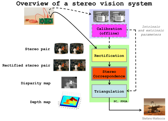 1. 图像采集
双目相机采集 左右目图像 2. 双目标定通过 双目标定工具 对双目相机进行标定,得到如下结果参数: 内参外参相机矩阵 K 1 , K 2 K_1, K_2 K1,K2旋转矩阵 R R R畸变系数 D 1 , D 2 D_1, D_2 D1,D2平移向量 t t t《Learning OpenCV》中对于 Translation 和 Rotation 的图示是这样的: 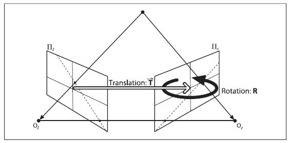
示例代码: cv::Matx33d K1, K2, R; cv::Vec3d T; cv::Vec4d D1, D2; int flag = 0; flag |= cv::fisheye::CALIB_RECOMPUTE_EXTRINSIC; flag |= cv::fisheye::CALIB_CHECK_COND; flag |= cv::fisheye::CALIB_FIX_SKEW; cv::fisheye::stereoCalibrate( obj_points_, img_points_l_, img_points_r_, K1, D1, K2, D2, img_size_, R, T, flag, cv::TermCriteria(3, 12, 0)); 3. 双目矫正双目矫正 主要包括两方面:畸变矫正 和 立体矫正 。 利用 OpenCV的函数,主要分为 stereoRectifyinitUndistortRectifyMapremap stereoRectify根据双目标定的结果 K 1 , K 2 , D 1 , D 2 , R , t K_1, K_2, D_1, D_2, R, t K1,K2,D1,D2,R,t,利用 OpenCV函数 stereoRectify,计算得到如下参数 左目 矫正矩阵(旋转矩阵) R 1 R_1 R1 (3x3)右目 矫正矩阵(旋转矩阵) R 2 R_2 R2 (3x3)左目 投影矩阵 P 1 P_1 P1 (3x4)右目 投影矩阵 P 2 P_2 P2 (3x4)disparity-to-depth 映射矩阵 Q Q Q (4x4)其中, 左右目投影矩阵(horizontal stereo, c x 1 ′ = c x 2 ′ {c_x}_1'={c_x}_2' cx1′=cx2′ if CV_CALIB_ZERO_DISPARITY is set) P 1 = [ f ′ 0 c x 1 ′ 0 0 f ′ c y ′ 0 0 0 1 0 ] P_1 = \begin{bmatrix} f' & 0 & {c_x}_1' & 0 \\ 0 & f' & c_y' & 0 \\ 0 & 0 & 1 & 0 \end{bmatrix} P1=⎣ ⎡f′000f′0cx1′cy′1000⎦ ⎤ P 2 = [ f ′ 0 c x 2 ′ t x ′ ⋅ f ′ 0 f ′ c y ′ 0 0 0 1 0 ] P_2 = \begin{bmatrix} f' & 0 & {c_x}_2' & t_x' \cdot f' \\ 0 & f' & c_y' & 0 \\ 0 & 0 & 1 & 0 \end{bmatrix} P2=⎣ ⎡f′000f′0cx2′cy′1tx′⋅f′00⎦ ⎤ where t x ′ = − B t_x' = -B tx′=−B disparity-to-depth 映射矩阵 Q = [ 1 0 0 − c x 1 ′ 0 1 0 − c y ′ 0 0 0 f ′ 0 0 − 1 t x ′ c x 1 ′ − c x 2 ′ t x ′ ] Q = \begin{bmatrix} 1 & 0 & 0 & -{c_x}_1' \\ 0 & 1 & 0 & -c_y' \\ 0 & 0 & 0 & f' \\ 0 & 0 & -\frac{1}{t_x'} & \frac{ {c_x}_1'-{c_x}_2'}{t_x'} \end{bmatrix} Q=⎣ ⎡10000100000−tx′1−cx1′−cy′f′tx′cx1′−cx2′⎦ ⎤ 通过 P 2 P_2 P2 可计算出 基线 长度: baseline = B = − t x ′ = − P 2 ( 03 ) f ′ \begin{aligned} \text{baseline} = B = - t_x' = - \frac{ {P_2}_{(03)} }{f'} \end{aligned} baseline=B=−tx′=−f′P2(03) 示例代码: cv::Mat R1, R2, P1, P2, Q; cv::fisheye::stereoRectify( K1, D1, K2, D2, img_size_, R, T, R1, R2, P1, P2, Q, CV_CALIB_ZERO_DISPARITY, img_size_, 0.0, 1.1); CameraInfo DKRP参考:sensor_msgs/CameraInfo Message D: distortion parameters. For “plumb_bob”, the 5 parameters are: (k1, k2, t1, t2, k3)K: Intrinsic camera matrix for the raw (distorted) images. Projects 3D points in the camera coordinate frame to 2D pixel coordinates using the focal lengths (fx, fy) and principal point (cx, cy). K = [ f x 0 c x 0 f y c y 0 0 1 ] \mathbf{K} = \begin{bmatrix} f_x & 0 & c_x \\ 0 & f_y & c_y \\ 0 & 0 & 1 \end{bmatrix} K=⎣ ⎡fx000fy0cxcy1⎦ ⎤R: Rectification matrix (stereo cameras only). A rotation matrix aligning the camera coordinate system to the ideal stereo image plane so that epipolar lines in both stereo images are parallel.For monocular cameras R = I \mathbf{R} = \mathbf{I} R=IP: Projection/camera matrix. For monocular cameras P = [ f x 0 c x 0 0 f y c y 0 0 0 1 0 ] \mathbf{P} = \begin{bmatrix} f_x & 0 & c_x & 0 \\ 0 & f_y & c_y & 0 \\ 0 & 0 & 1 & 0 \end{bmatrix} P=⎣ ⎡fx000fy0cxcy1000⎦ ⎤For a stereo pair, the fourth column [Tx Ty 0]’ is related to the position of the optical center of the second camera in the first camera’s frame. We assume Tz = 0 so both cameras are in the same stereo image plane. The first camera P = [ f x ′ 0 c x ′ 0 0 f y ′ c y ′ 0 0 0 1 0 ] \mathbf{P} = \begin{bmatrix} f_x' & 0 & c_x' & 0 \\ 0 & f_y' & c_y' & 0 \\ 0 & 0 & 1 & 0 \end{bmatrix} P=⎣ ⎡fx′000fy′0cx′cy′1000⎦ ⎤The second camera P = [ f x ′ 0 c x ′ − f x ′ ⋅ B 0 f y ′ c y ′ 0 0 0 1 0 ] \mathbf{P} = \begin{bmatrix} f_x' & 0 & c_x' & -f_x' \cdot B \\ 0 & f_y' & c_y' & 0 \\ 0 & 0 & 1 & 0 \end{bmatrix} P=⎣ ⎡fx′000fy′0cx′cy′1−fx′⋅B00⎦ ⎤ Given a 3D point [ X Y Z ] ′ [X Y Z]' [XYZ]′, the projection ( x , y ) (x, y) (x,y) of the point onto the rectified image is given by:[ u v w ] = P ⋅ [ X Y Z 1 ] , { x = u w y = v w \begin{bmatrix} u \\ v \\ w \end{bmatrix} = \mathbf{P} \cdot \begin{bmatrix} X \\ Y \\ Z \\ 1 \end{bmatrix} , \quad \begin{cases} x = \frac{u}{w} \\ y = \frac{v}{w} \end{cases} ⎣ ⎡uvw⎦ ⎤=P⋅⎣ ⎡XYZ1⎦ ⎤,{x=wuy=wv initUndistortRectifyMap左右目 分别利用 OpenCV函数 initUndistortRectifyMap 计算 the undistortion and rectification transformation map,得到 左目map: m a p 1 l , m a p 2 l map^l_1, map^l_2 map1l,map2l右目map: m a p 1 r , m a p 2 r map^r_1, map^r_2 map1r,map2r示例代码: cv::fisheye::initUndistortRectifyMap(K1, D1, R1, P1, img_size, CV_16SC2, rect_map_[0][0], rect_map_[0][1]); cv::fisheye::initUndistortRectifyMap(K2, D2, R2, P2, img_size, CV_16SC2, rect_map_[1][0], rect_map_[1][1]); Remap左右目 分别利用 OpenCV函数 remap 并根据 左右目map 对左右目图像进行 去畸变 和 立体矫正,得到 左右目矫正图像 示例代码: cv::remap(img_l, img_rect_l, rect_map_[0][0], rect_map_[0][1], cv::INTER_LINEAR); cv::remap(img_r, img_rect_r, rect_map_[1][0], rect_map_[1][1], cv::INTER_LINEAR); 4. 立体匹配根据双目矫正图像,通过 BM或SGM等立体匹配算法 对其进行立体匹配,计算 视差图 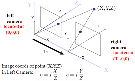 视差计算
视差计算
通过 OpenCV函数 stereoBM (block matching algorithm),生成 视差图(Disparity Map) (CV_16S or CV_32F) disparity map from stereoBM of OpenCV : It has the same size as the input images. When disptype == CV_16S, the map is a 16-bit signed single-channel image, containing disparity values scaled by 16. To get the true disparity values from such fixed-point representation, you will need to divide each disp element by 16. If disptype == CV_32F, the disparity map will already contain the real disparity values on output. So if you’ve chosen disptype = CV_16S during computation, you can access a pixel at pixel-position (X,Y) by: short pixVal = disparity.at(Y,X);, while the disparity value is float disparity = pixVal / 16.0f;; if you’ve chosen disptype = CV_32F during computation, you can access the disparity directly: float disparity = disparity.at(Y,X); Disparity MapDisparity map post-filtering 5. 三维重建(1)算法1:根据视差图,利用 f ′ f' f′ 和 B B B 通过几何关系计算 深度值,并利用相机内参计算 三维坐标 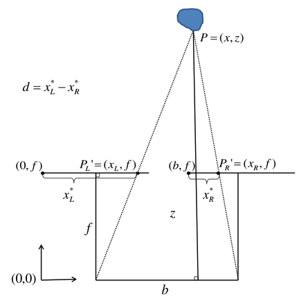
根据上图相似三角形关系,得 Z B = Z − f B − d w ⟹ Z = B f d w \frac{Z}{B} = \frac{Z-f}{B-d_w} \quad \Longrightarrow \quad Z = \frac{Bf}{d_w} BZ=B−dwZ−f⟹Z=dwBf 其中, f f f 和 d w d_w dw 分别为 成像平面的焦距和视差,单位均为 物理单位,将其转换为 像素单位,上式写为 Z = B f ′ d p Z = \frac{B f'}{d_p} Z=dpBf′ 其中, d p = ( O r − u r ) + ( u l − O l ) = ( u l − u r ) + ( O r − O l ) d_p = (O_r - u_r) + (u_l - O_l) = (u_l - u_r) + (O_r - O_l) dp=(Or−ur)+(ul−Ol)=(ul−ur)+(Or−Ol) 最终,深度计算公式如下,通过遍历图像可生成 深度图 Z = depth = B ⋅ f ′ d p with d p = disp ( u , v ) + ( c x 2 ′ − c x 1 ′ ) Z = \text{depth} = \frac{B \cdot f'}{d_p} \quad \text{with} \quad d_p = \text{disp}(u,v) + ({c_x}_2' - {c_x}_1') Z=depth=dpB⋅f′withdp=disp(u,v)+(cx2′−cx1′) 根据 小孔成像模型,已知 Z Z Z 和 相机内参 可计算出 三维点坐标,从而可生成 三维点云 { Z = depth = f ′ ⋅ B d p X = u − c x 1 ′ f ′ ⋅ Z Y = v − c y ′ f ′ ⋅ Z 或 { bd = B d p Z = depth = f ′ ⋅ bd X = ( u − c x 1 ′ ) ⋅ bd Y = ( u − c y ′ ) ⋅ bd \begin{aligned} \begin{cases} Z = \text{depth} = \frac{f' \cdot B}{d_p} \\ X = \frac{u-{c_x}_1'}{f'} \cdot Z \\ Y = \frac{v-{c_y}'}{f'} \cdot Z \end{cases} \end{aligned} \text{或} \begin{aligned} \begin{cases} \text{bd} = \frac{B}{d_p}\\ Z = \text{depth} = f' \cdot \text{bd} \\ X = (u-{c_x}_1') \cdot \text{bd} \\ Y = (u-{c_y}') \cdot \text{bd} \end{cases} \end{aligned} ⎩ ⎨ ⎧Z=depth=dpf′⋅BX=f′u−cx1′⋅ZY=f′v−cy′⋅Z或⎩ ⎨ ⎧bd=dpBZ=depth=f′⋅bdX=(u−cx1′)⋅bdY=(u−cy′)⋅bd 其中, disp ( u , v ) \text{disp}(u,v) disp(u,v) 代表 视差图 坐标值 (2)算法2:根据视差图,利用 Q Q Q 矩阵 计算 三维点坐标(reprojectImageTo3D) [ X ′ Y ′ Z ′ W ] = Q ⋅ [ u v disp ( u , v ) 1 ] \begin{bmatrix} X' \\ Y' \\ Z' \\ W \end{bmatrix} = Q \cdot \begin{bmatrix} u \\ v \\ \text{disp}(u,v) \\ 1 \end{bmatrix} ⎣ ⎡X′Y′Z′W⎦ ⎤=Q⋅⎣ ⎡uvdisp(u,v)1⎦ ⎤ 最终,三维点坐标为 [ X Y Z ] = [ X ′ W Y ′ W Z ′ W ] \begin{bmatrix} X \\ Y \\ Z \end{bmatrix} = \begin{bmatrix} \frac{X'}{W} \\[2ex] \frac{Y'}{W} \\[2ex] \frac{Z'}{W} \end{bmatrix} ⎣ ⎡XYZ⎦ ⎤=⎣ ⎡WX′WY′WZ′⎦ ⎤ 深度图 图像类型 单位meter --> 32FC1单位millimeter --> 16UC1 总结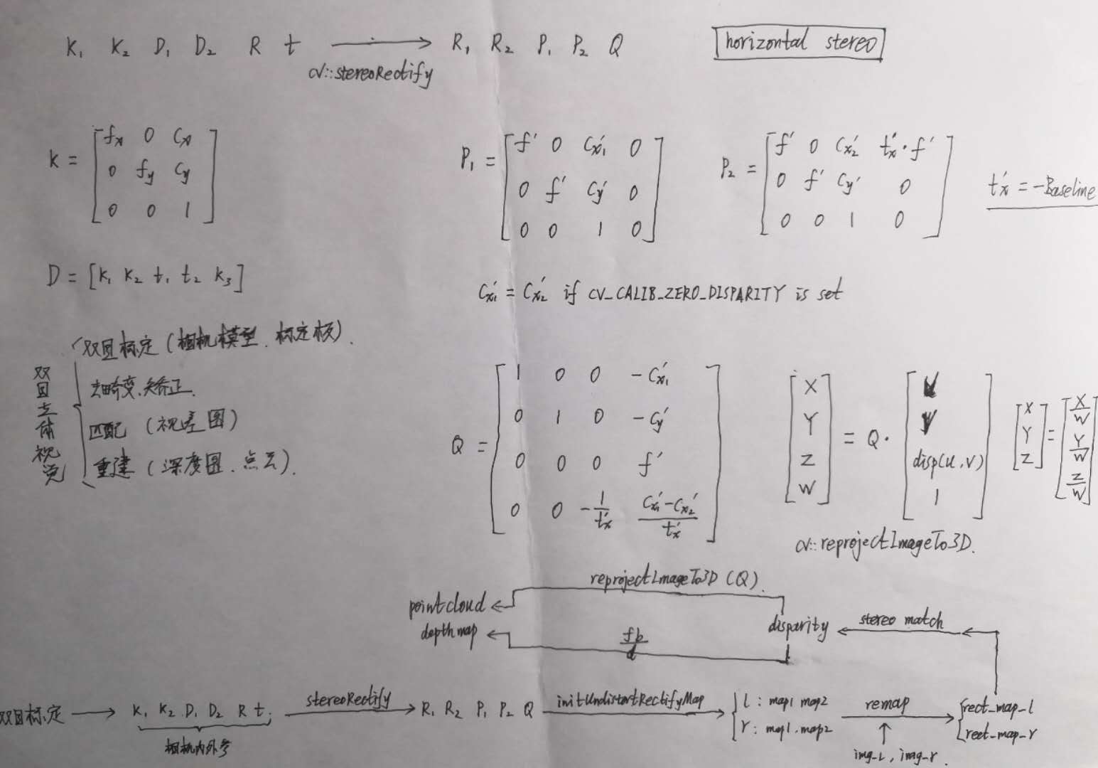
|
【本文地址】