| 电子模块 | 您所在的位置:网站首页 › 传感器及其接口技术参考文献有哪些 › 电子模块 |
电子模块
|
电子模块|心率血氧传感器模块MAX30102及其驱动代码
实物照片模块简介工作原理原理图及引脚说明STM32软件驱动IIC通信代码数值转换代码main函数
结果
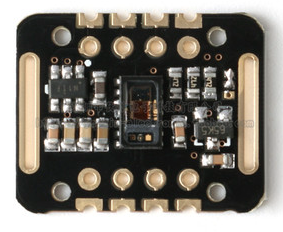
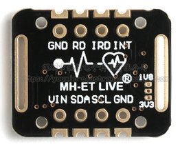
实物照片
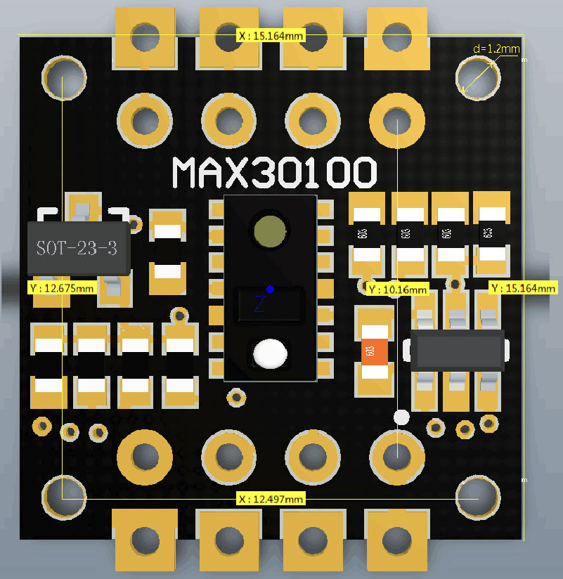
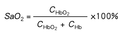
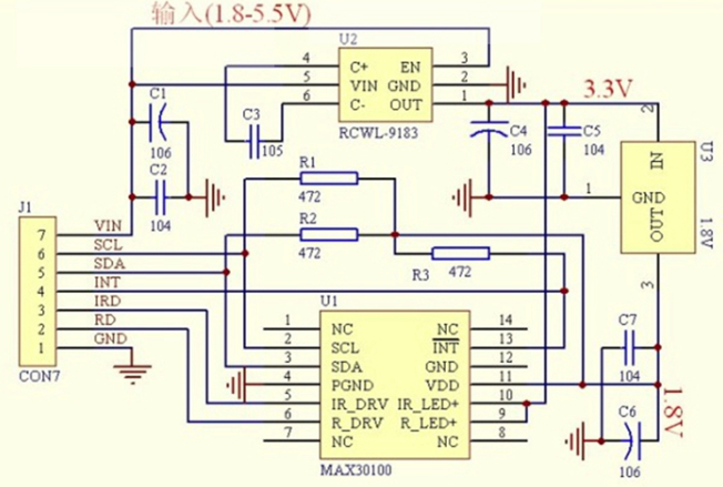
MAX30102是一个集成的脉搏血氧仪和心率监测仪生物传感器的模块。 它集成了一个红光LED和一个红外光LED、光电检测器、光器件,以及带环境光抑制的低噪声电子电路。 MAX30102采用一个1.8V电源和一个独立的5.0V用于内部LED的电源,应用于可穿戴设备进行心率和血氧采集检测,佩戴于手指点耳垂和手腕处。 标准的I2C兼容的通信接口可以将采集到的数值传输给Arduino、KL25Z、STM32、STC51等单片机进行心率和血氧计算。 此外,该芯片还可以通过软件关断模块,待机电流接近为零,实现电源始终维持供电状态。 主要参数: 产品名称MAX30102 心率模块LED峰值波长器660nm/880nmLED供电电压3.3 ~ 5V检测信号类型光反射信号(PPG)输出信号接口I2C接口通信接口电压1.8 ~ 3.3V ~ 5V(可选)产品尺寸: 光溶积法:利用人体组织在血管搏动时造成透光率不同来进行脉搏和血氧饱和度测量 光源:采用对动脉血中痒合血红蛋白(HbO2)和血红蛋白(Hb)有选择性的特定波长的发光二极管 透光率转化为电信号:动脉搏动充血容积变化导致这束光的透光率发送改变,此时由光电变换接收经人体组织反射光线,转变为电信号并将其放大输出。
使用STM32F103C8T6最小系统开发板验证。 接线如下: MAX30102模块接口:PB9-SDA,PB8-SCL,PB7-INT PA2/PA3为串口传输口TX和RX,波特率设置为115200 PC13为显示LED IIC通信代码 #include "mbed.h" #include "MAX30102.h" I2C i2c(I2C_SDA, I2C_SCL);//SDA-PB9,SCL-PB8 bool maxim_max30102_write_reg(uint8_t uch_addr, uint8_t uch_data) /** * \brief Write a value to a MAX30102 register * \par Details * This function writes a value to a MAX30102 register * * \param[in] uch_addr - register address * \param[in] uch_data - register data * * \retval true on success */ { char ach_i2c_data[2]; ach_i2c_data[0]=uch_addr; ach_i2c_data[1]=uch_data; if(i2c.write(I2C_WRITE_ADDR, ach_i2c_data, 2, false)==0) return true; else return false; } bool maxim_max30102_read_reg(uint8_t uch_addr, uint8_t *puch_data) /** * \brief Read a MAX30102 register * \par Details * This function reads a MAX30102 register * * \param[in] uch_addr - register address * \param[out] puch_data - pointer that stores the register data * * \retval true on success */ { char ch_i2c_data; ch_i2c_data=uch_addr; if(i2c.write(I2C_WRITE_ADDR, &ch_i2c_data, 1, true)!=0) return false; if(i2c.read(I2C_READ_ADDR, &ch_i2c_data, 1, false)==0) { *puch_data=(uint8_t) ch_i2c_data; return true; } else return false; } bool maxim_max30102_init() /** * \brief Initialize the MAX30102 * \par Details * This function initializes the MAX30102 * * \param None * * \retval true on success */ { if(!maxim_max30102_write_reg(REG_INTR_ENABLE_1,0xc0)) // INTR setting return false; if(!maxim_max30102_write_reg(REG_INTR_ENABLE_2,0x00)) return false; if(!maxim_max30102_write_reg(REG_FIFO_WR_PTR,0x00)) //FIFO_WR_PTR[4:0] return false; if(!maxim_max30102_write_reg(REG_OVF_COUNTER,0x00)) //OVF_COUNTER[4:0] return false; if(!maxim_max30102_write_reg(REG_FIFO_RD_PTR,0x00)) //FIFO_RD_PTR[4:0] return false; if(!maxim_max30102_write_reg(REG_FIFO_CONFIG,0x0f)) //sample avg = 1, fifo rollover=false, fifo almost full = 17 return false; if(!maxim_max30102_write_reg(REG_MODE_CONFIG,0x03)) //0x02 for Red only, 0x03 for SpO2 mode 0x07 multimode LED return false; if(!maxim_max30102_write_reg(REG_SPO2_CONFIG,0x27)) // SPO2_ADC range = 4096nA, SPO2 sample rate (100 Hz), LED pulseWidth (400uS) return false; if(!maxim_max30102_write_reg(REG_LED1_PA,0x24)) //Choose value for ~ 7mA for LED1 return false; if(!maxim_max30102_write_reg(REG_LED2_PA,0x24)) // Choose value for ~ 7mA for LED2 return false; if(!maxim_max30102_write_reg(REG_PILOT_PA,0x7f)) // Choose value for ~ 25mA for Pilot LED return false; return true; } bool maxim_max30102_read_fifo(uint32_t *pun_red_led, uint32_t *pun_ir_led) /** * \brief Read a set of samples from the MAX30102 FIFO register * \par Details * This function reads a set of samples from the MAX30102 FIFO register * * \param[out] *pun_red_led - pointer that stores the red LED reading data * \param[out] *pun_ir_led - pointer that stores the IR LED reading data * * \retval true on success */ { uint32_t un_temp; unsigned char uch_temp; *pun_red_led=0; *pun_ir_led=0; char ach_i2c_data[6]; //read and clear status register maxim_max30102_read_reg(REG_INTR_STATUS_1, &uch_temp); maxim_max30102_read_reg(REG_INTR_STATUS_2, &uch_temp); ach_i2c_data[0]=REG_FIFO_DATA; if(i2c.write(I2C_WRITE_ADDR, ach_i2c_data, 1, true)!=0) return false; if(i2c.read(I2C_READ_ADDR, ach_i2c_data, 6, false)!=0) { return false; } un_temp=(unsigned char) ach_i2c_data[0]; un_temp uint32_t un_ir_mean ,un_only_once ; int32_t k ,n_i_ratio_count; int32_t i, s, m, n_exact_ir_valley_locs_count ,n_middle_idx; int32_t n_th1, n_npks,n_c_min; int32_t an_ir_valley_locs[15] ; int32_t an_exact_ir_valley_locs[15] ; int32_t an_dx_peak_locs[15] ; int32_t n_peak_interval_sum; int32_t n_y_ac, n_x_ac; int32_t n_spo2_calc; int32_t n_y_dc_max, n_x_dc_max; int32_t n_y_dc_max_idx, n_x_dc_max_idx; int32_t an_ratio[5],n_ratio_average; int32_t n_nume, n_denom ; // remove DC of ir signal un_ir_mean =0; for (k=0 ; k an_dx[k] = ( an_dx[k]+an_dx[k+1])/2 ; } // hamming window // flip wave form so that we can detect valley with peak detector for ( i=0 ; i s -= an_dx[k] *auw_hamm[k-i] ; } an_dx[i]= s/ (int32_t)1146; // divide by sum of auw_hamm } n_th1=0; // threshold calculation for ( k=0 ; k for (k=1; k an_x[k] = pun_ir_buffer[k] ; an_y[k] = pun_red_buffer[k] ; } // find precise min near an_ir_valley_locs n_exact_ir_valley_locs_count =0; for(k=0 ; k for(i= m-5;i un_only_once =0; } n_c_min= an_x[i] ; an_exact_ir_valley_locs[k]=i; } if (un_only_once ==0) n_exact_ir_valley_locs_count ++ ; } } if (n_exact_ir_valley_locs_count an_x[k]=( an_x[k]+an_x[k+1]+ an_x[k+2]+ an_x[k+3])/(int32_t)4; an_y[k]=( an_y[k]+an_y[k+1]+ an_y[k+2]+ an_y[k+3])/(int32_t)4; } //using an_exact_ir_valley_locs , find ir-red DC andir-red AC for SPO2 calibration ratio //finding AC/DC maximum of raw ir * red between two valley locations n_ratio_average =0; n_i_ratio_count =0; for(k=0; k *pn_spo2 = -999 ; // do not use SPO2 since valley loc is out of range *pch_spo2_valid = 0; return; } } // find max between two valley locations // and use ratio betwen AC compoent of Ir & Red and DC compoent of Ir & Red for SPO2 for (k=0; k for (i=an_exact_ir_valley_locs[k]; in_x_dc_max =an_x[i];n_x_dc_max_idx =i; } if (an_y[i]> n_y_dc_max) {n_y_dc_max =an_y[i];n_y_dc_max_idx=i;} } n_y_ac= (an_y[an_exact_ir_valley_locs[k+1]] - an_y[an_exact_ir_valley_locs[k] ] )*(n_y_dc_max_idx -an_exact_ir_valley_locs[k]); //red n_y_ac= an_y[an_exact_ir_valley_locs[k]] + n_y_ac/ (an_exact_ir_valley_locs[k+1] - an_exact_ir_valley_locs[k]) ; n_y_ac= an_y[n_y_dc_max_idx] - n_y_ac; // subracting linear DC compoenents from raw n_x_ac= (an_x[an_exact_ir_valley_locs[k+1]] - an_x[an_exact_ir_valley_locs[k] ] )*(n_x_dc_max_idx -an_exact_ir_valley_locs[k]); // ir n_x_ac= an_x[an_exact_ir_valley_locs[k]] + n_x_ac/ (an_exact_ir_valley_locs[k+1] - an_exact_ir_valley_locs[k]); n_x_ac= an_x[n_y_dc_max_idx] - n_x_ac; // subracting linear DC compoenents from raw n_nume=( n_y_ac *n_x_dc_max)>>7 ; //prepare X100 to preserve floating value n_denom= ( n_x_ac *n_y_dc_max)>>7; if (n_denom>0 && n_i_ratio_count n_spo2_calc= uch_spo2_table[n_ratio_average] ; *pn_spo2 = n_spo2_calc ; *pch_spo2_valid = 1;// float_SPO2 = -45.060*n_ratio_average* n_ratio_average/10000 + 30.354 *n_ratio_average/100 + 94.845 ; // for comparison with table } else{ *pn_spo2 = -999 ; // do not use SPO2 since signal ratio is out of range *pch_spo2_valid = 0; } } void maxim_find_peaks(int32_t *pn_locs, int32_t *pn_npks, int32_t *pn_x, int32_t n_size, int32_t n_min_height, int32_t n_min_distance, int32_t n_max_num) /** * \brief Find peaks * \par Details * Find at most MAX_NUM peaks above MIN_HEIGHT separated by at least MIN_DISTANCE * * \retval None */ { maxim_peaks_above_min_height( pn_locs, pn_npks, pn_x, n_size, n_min_height ); maxim_remove_close_peaks( pn_locs, pn_npks, pn_x, n_min_distance ); *pn_npks = min( *pn_npks, n_max_num ); } void maxim_peaks_above_min_height(int32_t *pn_locs, int32_t *pn_npks, int32_t *pn_x, int32_t n_size, int32_t n_min_height) /** * \brief Find peaks above n_min_height * \par Details * Find all peaks above MIN_HEIGHT * * \retval None */ { int32_t i = 1, n_width; *pn_npks = 0; while (i // find left edge of potential peaks n_width = 1; while (i+n_width pn_x[i+n_width] && (*pn_npks) int32_t i, j, n_old_npks, n_dist; /* Order peaks from large to small */ maxim_sort_indices_descend( pn_x, pn_locs, *pn_npks ); for ( i = -1; i n_dist = pn_locs[j] - ( i == -1 ? -1 : pn_locs[i] ); // lag-zero peak of autocorr is at index -1 if ( n_dist > n_min_distance || n_dist n_temp = pn_x[i]; for (j = i; j > 0 && n_temp n_temp = pn_indx[i]; for (j = i; j > 0 && pn_x[n_temp] > pn_x[pn_indx[j-1]]; j--) pn_indx[j] = pn_indx[j-1]; pn_indx[j] = n_temp; } } main函数 #include "stm32f103c8t6.h" #include "mbed.h" #include "algorithm.h" #include "MAX30102.h" #define MAX_BRIGHTNESS 255 uint32_t aun_ir_buffer[500]; //IR LED sensor data int32_t n_ir_buffer_length; //data length uint32_t aun_red_buffer[500]; //Red LED sensor data int32_t n_sp02; //SPO2 value int8_t ch_spo2_valid; //indicator to show if the SP02 calculation is valid int32_t n_heart_rate; //heart rate value int8_t ch_hr_valid; //indicator to show if the heart rate calculation is valid uint8_t uch_dummy; Serial pc(SERIAL_TX, SERIAL_RX); //initializes the serial port, TX-PA2, RX-PA3 PwmOut pwmled(PB_3); //initializes the pwm output PB3 that connects to the LED DigitalIn INT(PB_7); //pin PB7 connects to the interrupt output pin of the MAX30102 DigitalOut led(PC_13); //PC13 connects to the on board user LED // the setup routine runs once when you press reset: int main() { uint32_t un_min, un_max, un_prev_data; //variables to calculate the on-board LED brightness that reflects the heartbeats int i; int32_t n_brightness; float f_temp; maxim_max30102_reset(); //resets the MAX30102 // initialize serial communication at 115200 bits per second: pc.baud(115200); pc.format(8,SerialBase::None,1); wait(1); //read and clear status register maxim_max30102_read_reg(0,&uch_dummy); //wait until the user presses a key // while(pc.readable()==0) // { // pc.printf("\x1B[2J"); //clear terminal program screen // pc.printf("Press any key to start conversion\n\r"); // wait(1); // } // uch_dummy=getchar(); maxim_max30102_init(); //initializes the MAX30102 n_brightness=0; un_min=0x3FFFF; un_max=0; n_ir_buffer_length=500; //buffer length of 100 stores 5 seconds of samples running at 100sps //read the first 500 samples, and determine the signal range for(i=0;i i=0; un_min=0x3FFFF; un_max=0; //dumping the first 100 sets of samples in the memory and shift the last 400 sets of samples to the top for(i=100;i un_prev_data=aun_red_buffer[i-1]; while(INT.read()==1); maxim_max30102_read_fifo((aun_red_buffer+i), (aun_ir_buffer+i)); if(aun_red_buffer[i]>un_prev_data)//just to determine the brightness of LED according to the deviation of adjacent two AD data { f_temp=aun_red_buffer[i]-un_prev_data; f_temp/=(un_max-un_min); f_temp*=MAX_BRIGHTNESS; n_brightness-=(int)f_temp; if(n_brightness |
【本文地址】
公司简介
联系我们