| 【树莓派 Pico 基于Arduino IDE编程开发】 | 您所在的位置:网站首页 › pico开发环境 › 【树莓派 Pico 基于Arduino IDE编程开发】 |
【树莓派 Pico 基于Arduino IDE编程开发】
|
【树莓派 Pico 基于Arduino IDE编程开发】
1.前言2. 目标3. 准备好 Arduino IDE3.1 安装Pico开发板3.2 上传示例程序
4. 实验效果
1.前言
树莓派 Pico 是2020年树莓派基金会推出的微控制器(MCU)产品,其功能丰富且成本低,非常适合我们的项目。 我们很多人都喜欢😍😍😍使用 Arduino IDE 来对微控制器进行编程。 Python 和 C/C++ 都非常适合来进行 Pico 的编程。 详情见【树莓派 Pico 和 Pico W】
而下面的要介绍的是使用 Arduino IDE 来作为树莓派 Pico 的开发环境,就和开发 Arduino 程序一样去做 Pico 上的开发,将树莓派 Pico 集成到 Arduino 的生态中。这样做的原因之一是可以直接使用丰富的 Arduino 底层库、允许集成模块、传感器和其他复杂的东西,而无需从头开始编写所有代码。 😀😀😀 所以事不宜迟,让我们开始吧! 👻👻👻 3. 准备好 Arduino IDE 3.1 安装Pico开发板通过菜单 Tools>Boards>Boards Manager 来搜索开发板,输入关键词 ‘pico’ 找到并下载安装到 Arduino IDE。 打开文件>示例>01.basic>Blink例程 说明LED_BUILTIN对应Pico的GPIO25 这里要注意的是,当Pico开发板成功连接到电脑后,我们无须再选择串行端口。这是因为电脑在第一次上传程序时会写入.uf2文件到Pico开发板,之后电脑会自动选择串行端口。 将 Pico 连上电脑,菜单 Tools>Port 中选择 Pico 对应的 COM 端口。
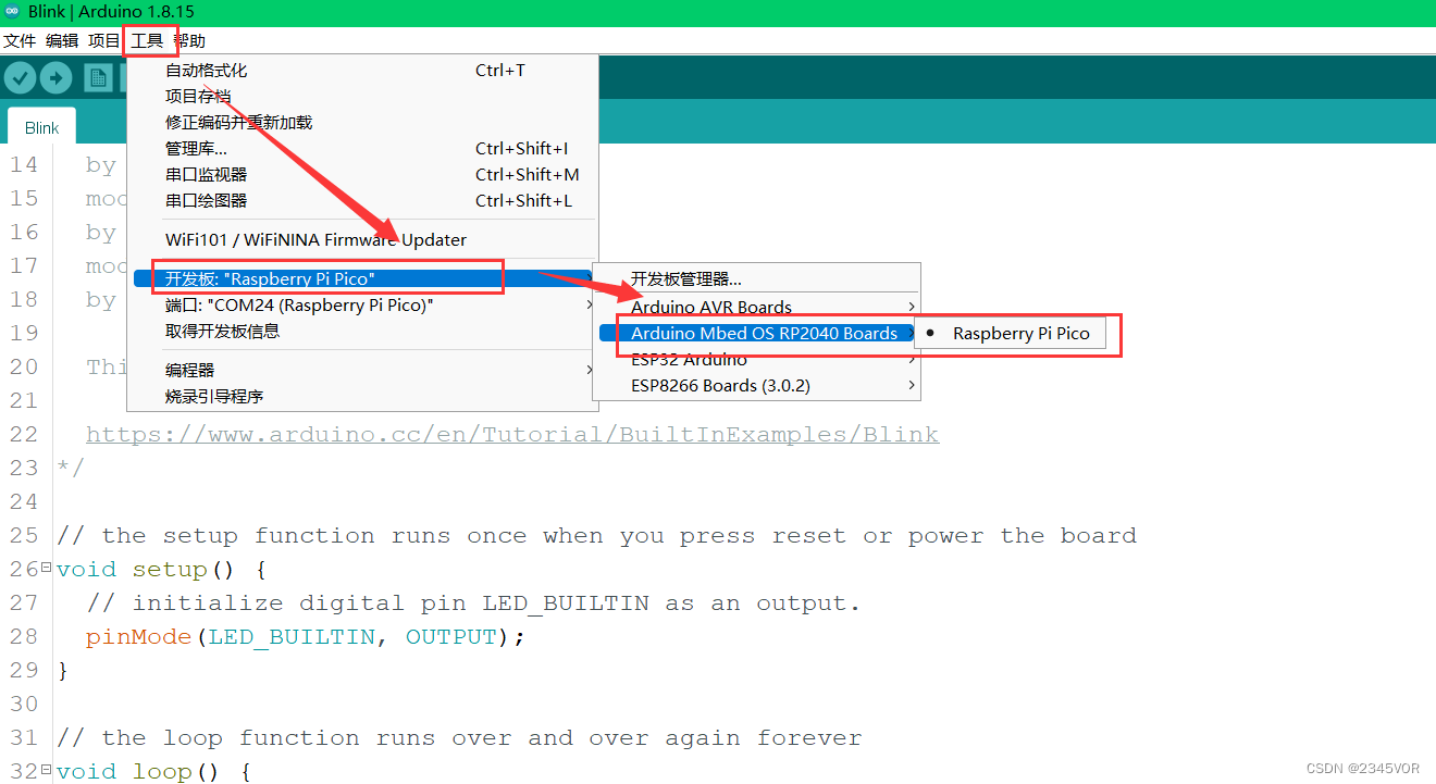
在工具Tools>Boards>OS RP2040 Board中选择Pi Pico ,点击 Upload 上传到 Pico。 当 IDE 显示已经上传完成,就可以看到 Pico 板载的 LED 开始闪烁。 还有Fade示例也可用,GPIO9加一个灯实现对应的呼吸效果 /* Fade This example shows how to fade an LED on pin 9 using the analogWrite() function. The analogWrite() function uses PWM, so if you want to change the pin you're using, be sure to use another PWM capable pin. On most Arduino, the PWM pins are identified with a "~" sign, like ~3, ~5, ~6, ~9, ~10 and ~11. This example code is in the public domain. https://www.arduino.cc/en/Tutorial/BuiltInExamples/Fade */ int led = 9; // the PWM pin the LED is attached to int brightness = 0; // how bright the LED is int fadeAmount = 5; // how many points to fade the LED by // the setup routine runs once when you press reset: void setup() { // declare pin 9 to be an output: pinMode(led, OUTPUT); } // the loop routine runs over and over again forever: void loop() { // set the brightness of pin 9: analogWrite(led, brightness); // change the brightness for next time through the loop: brightness = brightness + fadeAmount; // reverse the direction of the fading at the ends of the fade: if (brightness = 255) { fadeAmount = -fadeAmount; } // wait for 30 milliseconds to see the dimming effect delay(30); }参考文献: 使用 Arduino IDE 为树莓派 Pico 编程开发树莓派Pico开发板Arduino IDE开发环境安装与使用 |


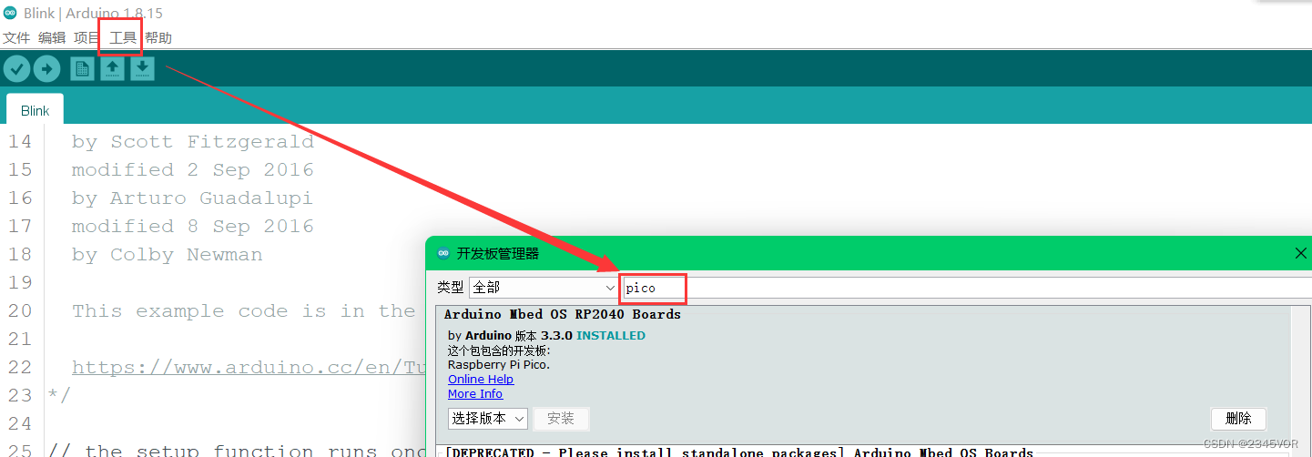 点击安装Arduino Mbed os RP2040 Boards 开发板,安装完成如上图
 源码如下 Blink
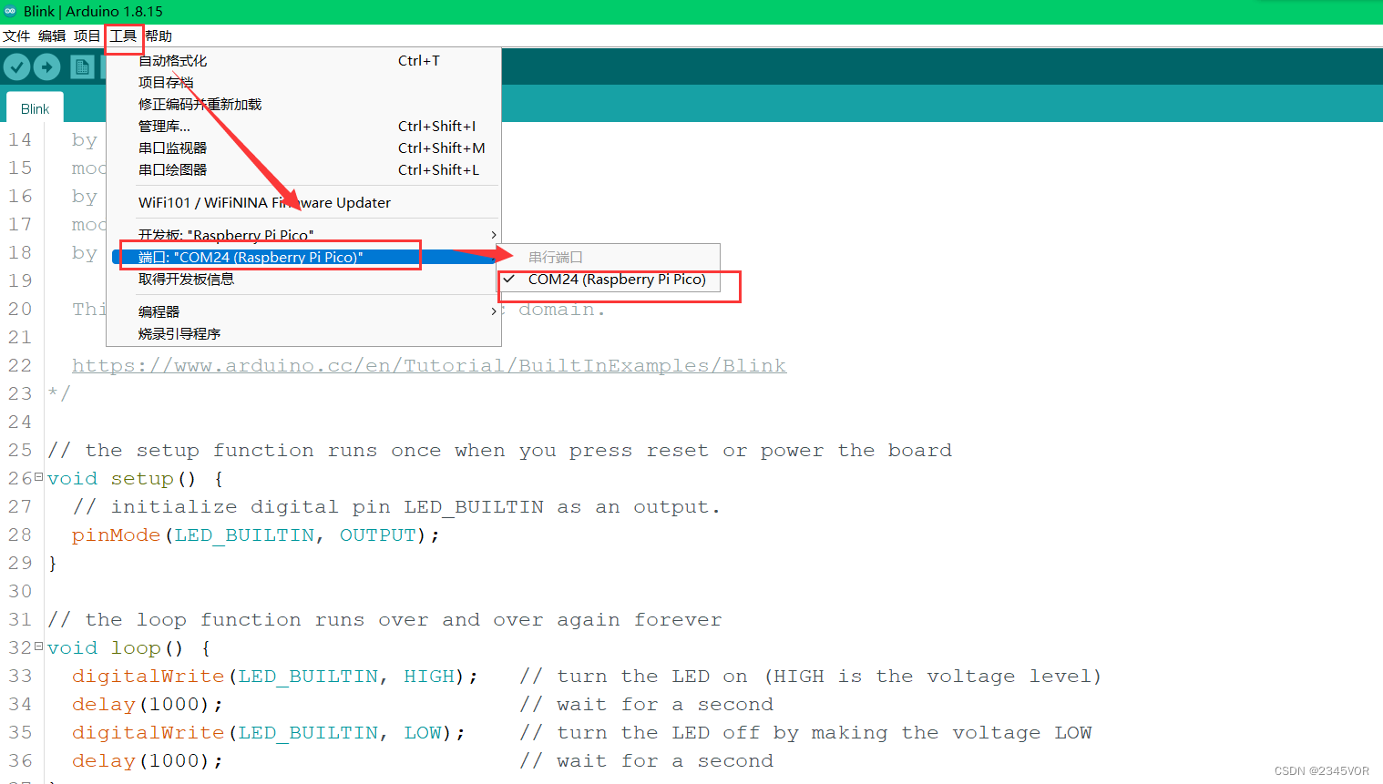
【本文地址】