| GPIO与IOMUX | 您所在的位置:网站首页 › 设置pin是干的 › GPIO与IOMUX |
GPIO与IOMUX
|
GPIO与IOMUX
1 GPIO1.1 何为GPIO?1.2 GPIO常用寄存器1.2.1 GPIO direction register (GPIOx_GDIR)1.2.2 GPIO data register (GPIOx_DR)1.2.3 GPIO pad status register (GPIOx_PSR)
1.3 GPIO时钟1.4 GPIO逻辑结构
2 IOMUX2.1 何为IOMUX2.2 IOMUX逻辑图2.2.1 IOMUX和PAD2.2.2 PAD和Module
3 IOMUX设置PAD为GPIO实例3.1 寻找实例和对应的PAD3.1.1 设置SW_MUX_CTL_PAD_GPIO1_IO003.1.2 设置SW_PAD_CTL_PAD_GPIO1_IO003.1.3 设置实例GPIO1全组属性
1 GPIO
1.1 何为GPIO?
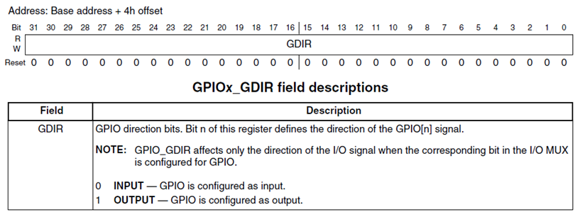
GPIO只是一个CPU内提供的一种功能外设,CPU外部的I/O引脚会被赋予一种功能(GPIO、UART、I2C等);该功能由CPU内外设提供,具体是什么功能由IOMUX单元(I/O复用选择器)控制。 GPIO(General Purpose Input/Output)是芯片内的外设功能模块 ,每个GPIO外设连接到了外部的I/O引脚上,和GPIO外设相连的I/O引脚(I/O引脚相较于GPIO更加远离CPU) 起着通用输入输出的功能,所以被称为 GPIO 引脚。 但是,I/O引脚不仅和GPIO外设相连,还可以和芯片内部其它外设相连,比如和UART、IIC、SPI等外设相连作为通信外设的接口引脚,和定时器相连作为PWM输出引脚,等等。 1.2 GPIO常用寄存器GPIO特性: 通用输入/输出逻辑功能: • 使用数据寄存器进行特定数据输出(GPIO_DR) • 控制信号方向(GPIO_GDIR) • 使能核心通过读取pad寄存器对应的采样输入通讯信号(GPIO_PSR). GPIO interrupt capabilities: • 支持32种中断 • 定义中断沿 1.2.1 GPIO direction register (GPIOx_GDIR)A GPIO signal can operate as a general-purpose input/output when the IOMUX is set to GPIO mode. GPIO direction register (GPIO_GDIR)来确定是GPIO是输入还是输出。当为输入模式bit=0,对应输入情况由GPIO_PSR位读取确定。
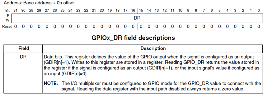
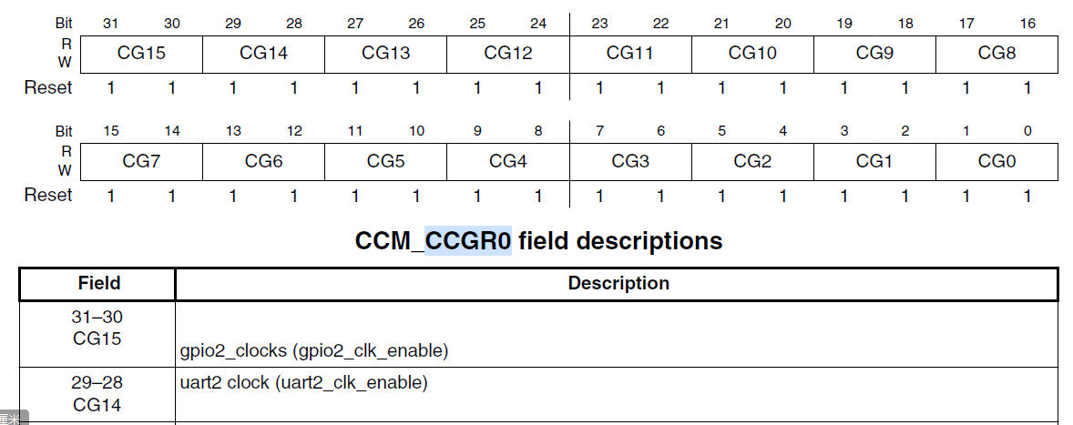
32位寄存器储存数据,时刻准备加载到output line中。 GPIO模式由IOMUX确定,由GPIO_GDIR确定输入还是输出;DR寄存器数据加载入output中。 • If GDIR[n] is set and IOMUXC input mode is GPIO, then reading DR[n] returns the contents of DR[n]. • If GDIR[n] is cleared and IOMUXC input mode is GPIO, then reading DR[n] returns the corresponding input signal’s value. • If GDIR[n] is set and IOMUXC input mode is not GPIO, then reading DR[n] returns the contents of DR[n]. • If GDIR[n] is cleared and IOMUXC input mode is not GPIO, then reading DR[n] always returns zero. GPIO_PSR is a read-only register. Each bit stores the value of the corresponding input signal (as configured in the IOMUX). This register is clocked with the ipg_clk_s clock, meaning that the input signal is sampled only when accessing this location. Two wait states are required any time this register is accessed for synchronization. 1.3 GPIO时钟 先查阅手册,找到GPIO的时钟隶属于哪一组;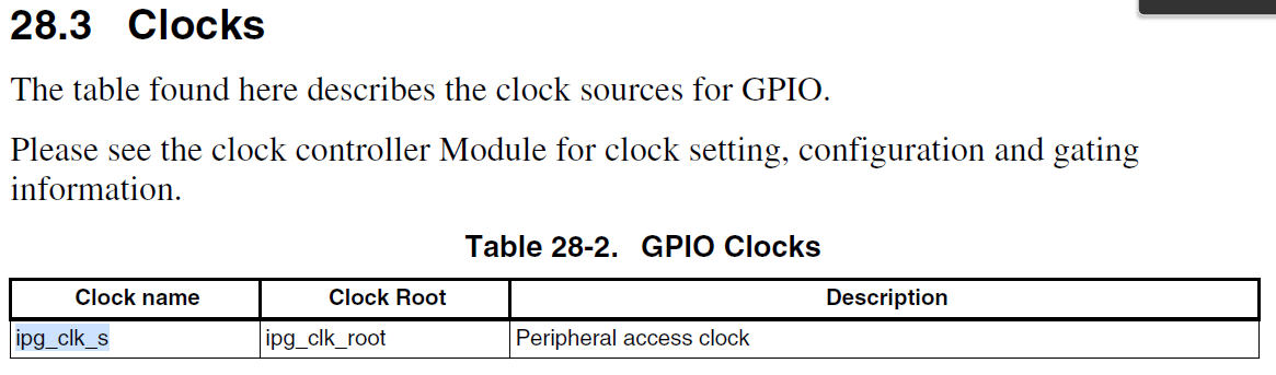 去到Clock章节寻找对应的clock name:IPG_CLK_S 去到Clock章节寻找对应的clock name:IPG_CLK_S 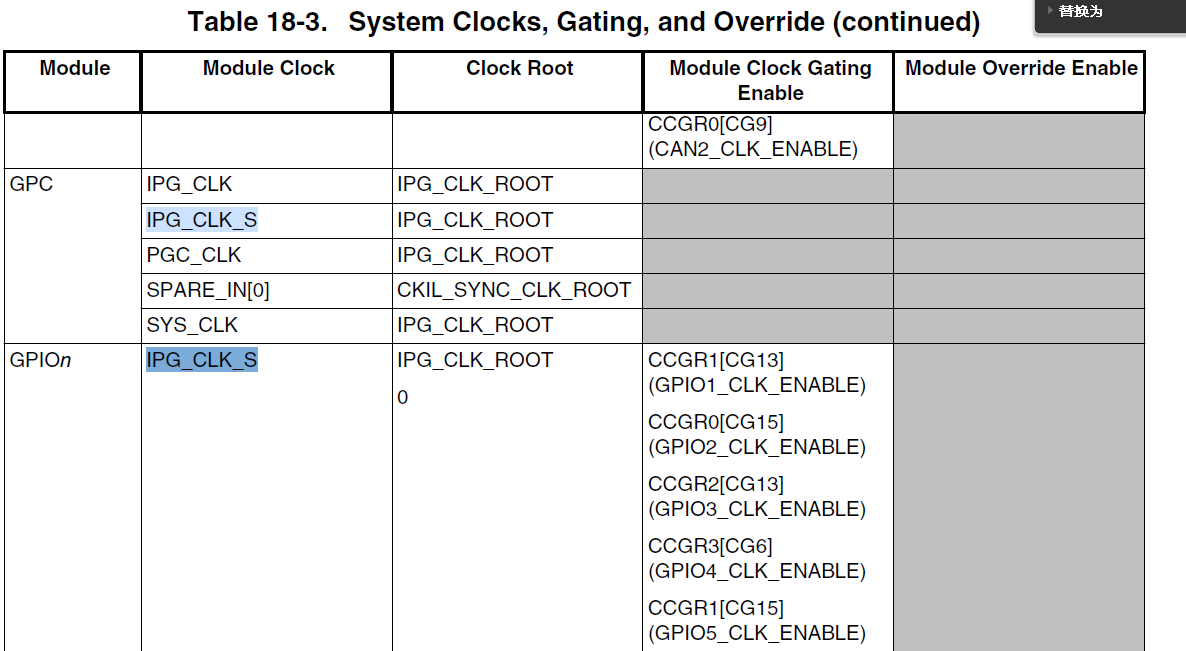 去查对应的寄存器,以CCM_CCGR0为例: 去查对应的寄存器,以CCM_CCGR0为例:
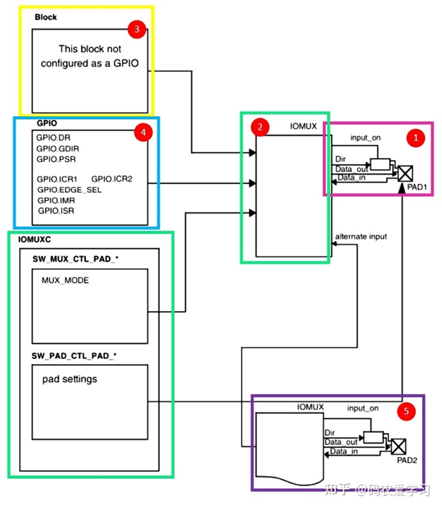
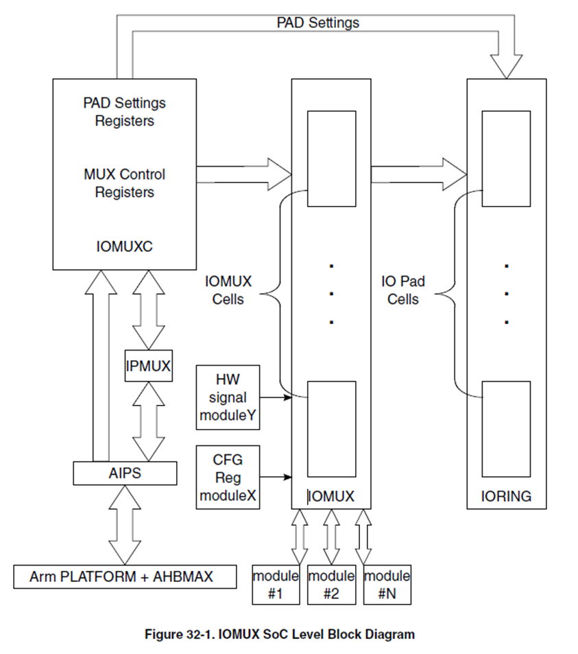
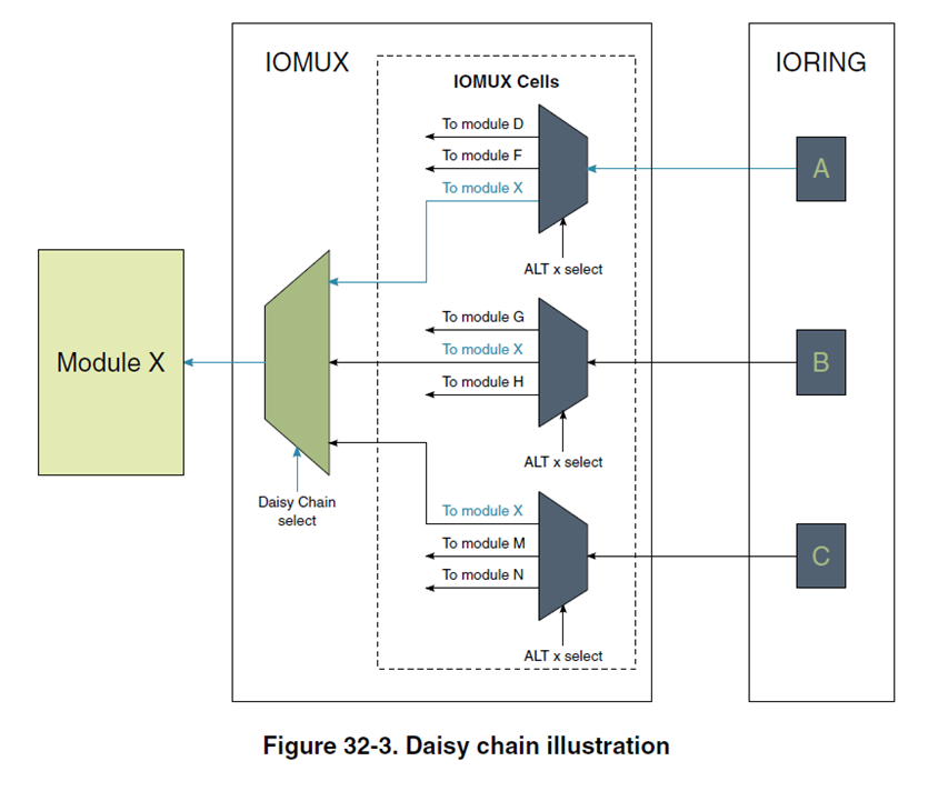
它是CPU内部的控制器,负责给PAD赋予不同功能,使得PAD在外部展现出不同的功能;而PAD的外部就是IO引脚;因此实现IO复用。 2.2 IOMUX逻辑图 2.2.1 IOMUX和PAD
位于手册 Muxing Options: 以实例GPIO1组下端口IO1为例:Pad为GPIO1_IO01,模式为ALT5。 3.1.1 设置SW_MUX_CTL_PAD_GPIO1_IO00所有的Pad设置均是如此,先设置SW_MUX_CTL_PAD_xxx。
设置这个Pad的属性,比如驱动能力、是否使用上下拉电阻等。 3.1.3 设置实例GPIO1全组属性注意:对于单个引脚(IO和Pad)需要设置它的功能(属于哪个module)和引脚属性,但是设置只是针对当前引脚的功能和属性;每一个引脚隶属于一个Instance(本质上是module外设),需要设置整个module(实例组)的属性。 GPIO实例需要设定的属性: |

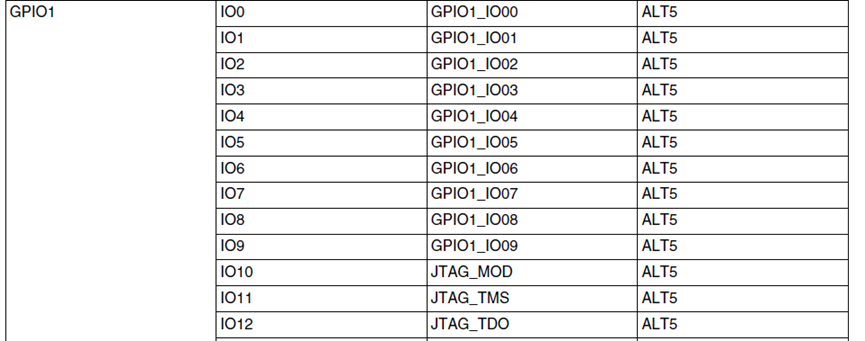 从左到右分别为:实例(功能)、实例端口、PAD、PAD应该被设置为ALTx。 外部信号按模块实例分组的,每个信号的复用选项以及用于将信号路由到所选 PAD 的寄存器。
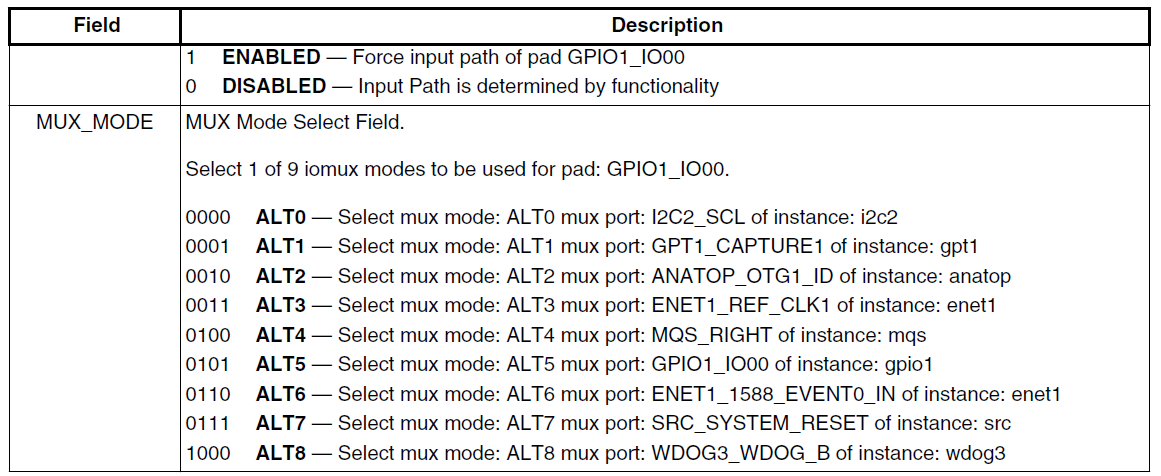 查手册,因此寄存器通过位运算设置低四位为:0101
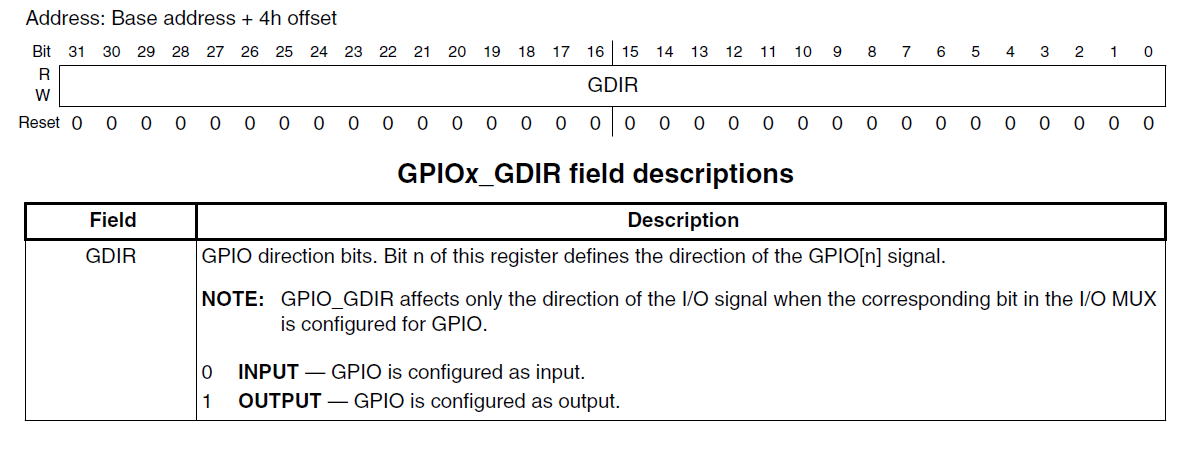 GPIOx_GDIR:每一个bit位的0/1表示一个GPIO实例的属性。
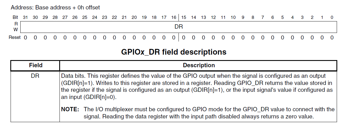
【本文地址】