| 工业相机与SCARA机械臂的坐标系标定 | 您所在的位置:网站首页 › 埃及手和机械臂谁厉害 › 工业相机与SCARA机械臂的坐标系标定 |
工业相机与SCARA机械臂的坐标系标定
|
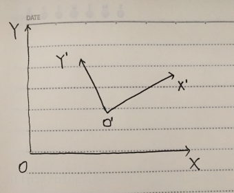
原文:https://blog.csdn.net/qq_36552550/article/details/79409242 注:感谢固高长江研究院徐工程师的技术讲解,以及matlab程序,机器人系统程序的提供。 在工业现场当中,相机拍摄到的图像有一个相机坐标系,而机器人自身也有一个机器人自身的坐标系,两者互相独立;当我们通过相机进行对物体进行拍摄,通过模式识别得到了目标物体在相机坐标系下的坐标位置,那么如何通过计算来让机器人知道目标物体在机器人坐标系的位置,以便机器人进行抓取操作呢? 这一章,首先进行标定原理的讲解,然后通过程序进行实现;最后,以洛阳理工学院实验室的固高工业智能相机及SCARA机械手为硬件基础,进行实验验证。 10.1 标定原理如图10-1所示,OXY为机器人坐标系,O’X’Y’是相机坐标系。 图10-1 机器人坐标系与相机坐标系示意图 当相机获取目标物体在相机坐标系下的坐标(imageP3.x,imageP3.y)时,如何进行计算得到对应在机器人坐标系下的坐标(robotP3.x,robotP3.y)呢? (为了对应后面程序,所以坐标名称直接使用下文中的程序变量名)
首先,需要通过两个已知坐标点进行标定。P1点在机器人坐标系下和相机坐标系下的坐标为(imageP1.x,imageP1.y),(robotP1.x,robotP1.y);P2点在机器人坐标系下和相机坐标系下的坐标为(imageP2.x,imageP2.y),(robotP2.x,robotP2.y)。 求得机器人坐标系下的向量robotP1P2以及相机坐标系下的向量imageP1P2: imageP1P2.x = imageP2.x - imageP1.x imageP1P2.y = imageP2.y - imageP1.y robotP1P2.x = robotP2.x - robotP1.x robotP1P2.y = robotP2.y - robotP1.y
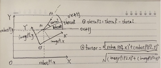
然后,根据这两个坐标点求得现实距离与图像像素之间的比例系数factor以及两个坐标系之间的偏转角thetaRI。 factor = sqrt(robotP1P2.x*robotP1P2.x + robotP1P2.y*robotP1P2.y)/ sqrt(imageP1P2.x*imageP1P2.x + imageP1P2.y*imageP1P2.x) 偏转角thetaRI的求取:如图10-2所示。 图10-2 偏转角求取示意图 先求得机器人坐标系下向量robotP1P2相对于x轴的偏转角thetaR,然后求得相机坐标系下的向量imageP1P2相对于x轴的偏转角thetaI;最后两者相减就是两个坐标系的偏转角thetaR。 thetaR = atan2((robotP2.y - robotP1.y) ,(robotP2.x - robotP1.x)) thetaI = atan2((imageP2.y - imageP1.y) , (imageP2.x - imageP1.x)) thetaRI = thetaR - thetaI
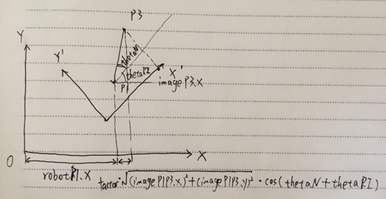
最后,根据比例系数factor以及偏转角thetaRI就可以对相机坐标系内的任意一个坐标进行机器人坐标系坐标转换。原理图如图10-3所示。 图10-3 坐标转换示意图 相机坐标系下的坐标(imageP3.x,imageP3.y),那么相机坐标系下的向量imageP1P3为 imageP1P3.x = imageP3.x - imageP1.x imageP1P3.y = imageP3.y - imageP1.y 还需要求得相机坐标系下的相对于x轴偏转角thetaN = atan2(imageP1P3.y, imageP1P3.x)。这样通过图10-3中的原理就可以得出机器人坐标系下的坐标了。 robotP3.x = factor*sqrt(imageP1P3.x*imageP1P3.x + imageP1P3.y*imageP1P3.y)* cos(thetaN + thetaRI) + robotP1.x robotP3.y = factor*sqrt(imageP1P3.x*imageP1P3.x + imageP1P3.y*imageP1P3.y)* sin(thetaN + thetaRI) + robotP1.y
得到最终的robotP3坐标就可以通信给机器人让机器人移动到该座标下,也就是目标物体的位置处。 10.2 标定程序实现完整的程序实现如下所示: /* 机器人坐标系与相机坐标系转换程序 第一步:记录A点的机器人坐标系下坐标以及图像坐标系下坐标,记录B点的机器人坐标系下坐标以及图像坐标系下坐标; 第二步:计算得到现实距离与图像像素之间的比例系数,以及两坐标系的偏转角; 前两步完成后,即完成了标定过程,接下来就可以根据一个新的点的图像坐标系下的坐标,求得该点的机器人坐标点; 第三步:输入一个图像坐标系下的点,程序自动得到机器人坐标下的点。 */ #include #include using namespace std; struct position { double x; double y; }; struct vector { double x; double y; }; int main() { //1 input the positions in the camera coodinate and robot coodinate position imageP1, imageP2, robotP1, robotP2; cout imageP1.x >> imageP1.y >> imageP2.x >> imageP2.y; cout robotP1.x >> robotP1.y >> robotP2.x >> robotP2.y; //2 caculate the factor and tangle vector imageP1P2, robotP1P2; imageP1P2.x = imageP2.x - imageP1.x; imageP1P2.y = imageP2.y - imageP1.y; robotP1P2.x = robotP2.x - robotP1.x; robotP1P2.y = robotP2.y - robotP1.y; double factor, thetaI, thetaR, thetaRI; factor = sqrt(robotP1P2.x*robotP1P2.x + robotP1P2.y*robotP1P2.y)/ sqrt(imageP1P2.x*imageP1P2.x + imageP1P2.y*imageP1P2.x); thetaR = atan2((robotP2.y - robotP1.y) ,(robotP2.x - robotP1.x)); thetaI = atan2((imageP2.y - imageP1.y) , (imageP2.x - imageP1.x)); thetaRI = thetaR - thetaI; cout |
【本文地址】