| 第2课 基于stm32f103c8t6的LED灯 (闪烁) | 您所在的位置:网站首页 › 呼吸灯闪烁设置 › 第2课 基于stm32f103c8t6的LED灯 (闪烁) |
第2课 基于stm32f103c8t6的LED灯 (闪烁)
|
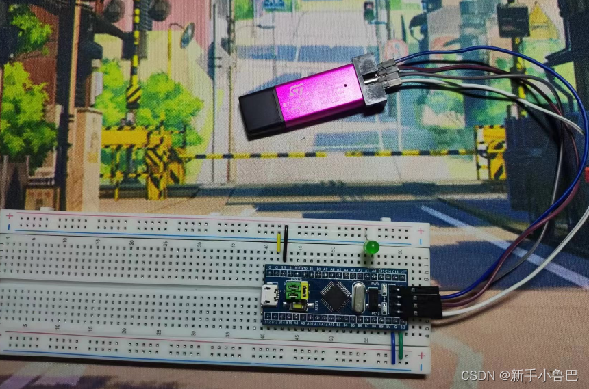
首先是硬件部分,如图 将所需元器件与面包板连接起来
程序部分 -------------------------------------------------------------------------------------------------------------------------------- #include "stm32f10x.h" // Device header #include "Delay.h" int main(void) { RCC_APB2PeriphClockCmd(RCC_APB2Periph_GPIOA, ENABLE); GPIO_InitTypeDef GPIO_InitStucture; GPIO_InitStucture.GPIO_Mode = GPIO_Mode_Out_PP; //推挽输出 高低电平均有驱动,开漏输出只有低电平驱动 GPIO_InitStucture.GPIO_Pin = GPIO_Pin_0; //0号引脚 GPIO_InitStucture.GPIO_Speed = GPIO_Speed_50MHz; //50mz的速度 GPIO_Init(GPIOA, &GPIO_InitStucture); // GPIO_SetBits(GPIOA, GPIO_Pin_0); //给高电平输出 // GPIO_ResetBits(GPIOA, GPIO_Pin_0); //给低电平输出 // GPIO_Write(GPIO_TypeDef* GPIOx, uint16_t PortVal); while(1) { // GPIO_ResetBits(GPIOA, GPIO_Pin_0); //与下面功能一致 // Delay_ms(500); // GPIO_SetBits(GPIOA, GPIO_Pin_0); // Delay_ms(500); GPIO_WriteBit(GPIOA, GPIO_Pin_0, Bit_RESET); //Bit_RESET给低电平,Bit_SET给高电平 Delay_ms(500); GPIO_WriteBit(GPIOA, GPIO_Pin_0, Bit_SET); //Bit_RESET给低电平,Bit_SET给高电平 Delay_ms(500); } } -------------------------------------------------------------------------------------------------------------------------------- 首先是 RCC_APB2PeriphClockCmd(RCC_APB2Periph_GPIOA, ENABLE);因为led灯连接的是PA0,我们就要先设置A的时钟RCC,连接的总线为APB2。 其次 定义一个GPIO_InitTypeDef 类型的结构体变量 GPIO_InitStucture。 使用结构体变量的“.”操作结构体的内部变量如下 GPIO_InitStucture.GPIO_Mode = GPIO_Mode_Out_PP; //推挽输出 高低电平均有驱动,开漏输出(OD)只有低电平驱动 GPIO_InitStucture.GPIO_Pin = GPIO_Pin_0; //0号引脚 GPIO_InitStucture.GPIO_Speed = GPIO_Speed_50MHz; //50mz的速度 最后,使用GPIO_Init函数,选中A口以及取GPIO_InitStucture的地址(即是其结构体内部的数据)。 GPIO_Init(GPIOA, &GPIO_InitStucture 输出操作,对brss和bss进行操作 // GPIO_SetBits(GPIOA, GPIO_Pin_0); //给高电平输出 // GPIO_ResetBits(GPIOA, GPIO_Pin_0); //给低电平输出 // GPIO_Write(GPIO_TypeDef* GPIOx, uint16_t PortVal); 延时需要在whlie(1)中进行,另外,可以从system文件夹将延时函数复制过来,方便使用
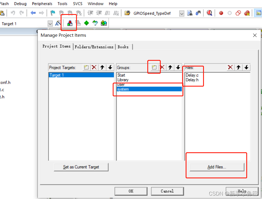
延时函数: -------------------------------------------------------------------------------------------------------------------------------- #include "stm32f10x.h" /** * @brief 微秒级延时 * @param xus 延时时长,范围:0~233015 * @retval 无 */ void Delay_us(uint32_t xus) { SysTick->LOAD = 72 * xus; //设置定时器重装值 SysTick->VAL = 0x00; //清空当前计数值 SysTick->CTRL = 0x00000005; //设置时钟源为HCLK,启动定时器 while(!(SysTick->CTRL & 0x00010000)); //等待计数到0 SysTick->CTRL = 0x00000004; //关闭定时器 } /** * @brief 毫秒级延时 * @param xms 延时时长,范围:0~4294967295 * @retval 无 */ void Delay_ms(uint32_t xms) { while(xms--) { Delay_us(1000); } } /** * @brief 秒级延时 * @param xs 延时时长,范围:0~4294967295 * @retval 无 */ void Delay_s(uint32_t xs) { while(xs--) { Delay_ms(1000); } } -------------------------------------------------------------------------------------------------------------------------------- 别忘了定义延时函数的头文件~ -------------------------------------------------------------------------------------------------------------------------------- #ifndef __DELAY_H #define __DELAY_H void Delay_us(uint32_t us); void Delay_ms(uint32_t ms); void Delay_s(uint32_t s); #endif #ifndef __DELAY_H #define __DELAY_H void Delay_us(uint32_t us); void Delay_ms(uint32_t ms); void Delay_s(uint32_t s); #endif -------------------------------------------------------------------------------------------------------------------------------- 编译成功,但是led并没有闪烁的时候,就要注意是不是线路接错了。 补充一下简单的小知识; 推挽输出其实在高低电平都有一定的驱动能力,但是开漏输出只有低电平有驱动能力,高电平则为高阻态,无驱动能力。 led灯的短脚为负极,长脚为正极 |
【本文地址】