| UE4地形的程序化生成【含源码】 | 您所在的位置:网站首页 › ue4绘制地形材质出现方块 › UE4地形的程序化生成【含源码】 |
UE4地形的程序化生成【含源码】
|
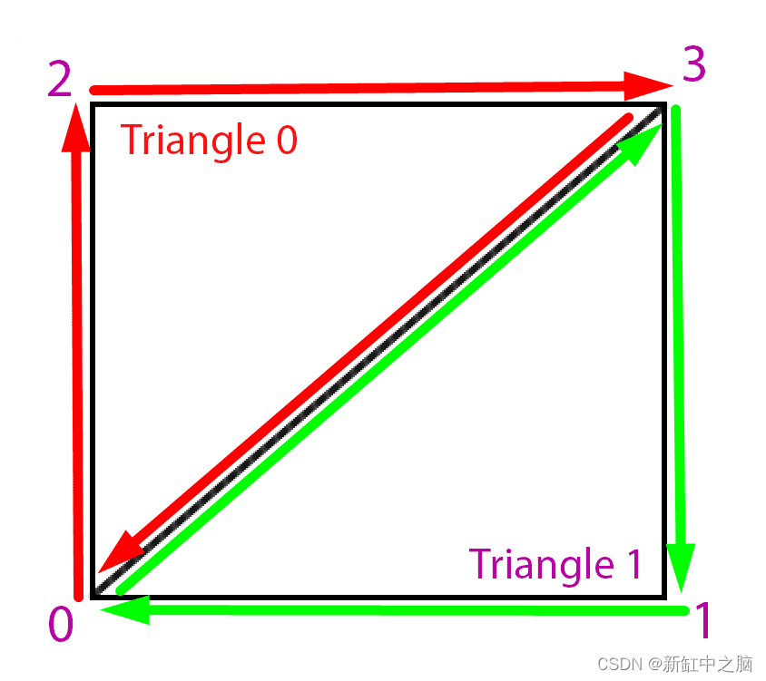
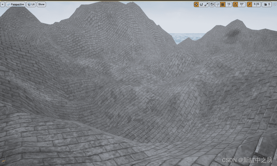
在前面的教程中,我们在虚幻引擎中添加了Perlin噪声,以便轻松地在代码/蓝图中复用。现在可以利用Perlin噪声来生成网格了。 经过一番研究,我发现了这个RuntimeMeshComponent,它可以在运行时生成网格(mesh),封装了一些底层的操作。 问题是,它仅适用于虚幻4.10-4.16,而我使用的是4.18。因此我决定为较新版本的虚幻引擎分叉并升级项目。 这个组件允许我们从一组顶点、三角形、法线等数据来生成网格。 2、什么是网格用RuntimeMeshComponent生成网格需要以下信息: 顶点:构成网格的所有单个点三角形:将顶点连接在一起以形成网格表面的三角形法线:每个顶点的法向量。它们垂直于由其顶点形成的三角形,用于照明目的切线:定义顶点纹理方向的 2D 矢量。UV:每个顶点的纹理坐标,介于 0 和 1 之间。顶点颜色:每个顶点的颜色让我们看一种非常简单的网格 — 由两个三角形组成的正方形: 顶点次序是从左到右,从下到上,所以第一个顶点是左下角,然后是右下角,然后是左上角和右上角。 三角形由逆时针排列的三个顶点组成,因此我们可以使两个三角形组成这个方形网格: 三角形 0 :0 -> 2 ->3->0三角形 1: 0 -> 3->1-> 0 3、在代码中生成顶点和三角形在代码中,顶点和三角形被定义为数组: 顶点数组是向量数组。数组中的每个值都是一个 3D 矢量,表示顶点的位置三角形数组是整数数组。数组中的每个值都是顶点数组的索引,该索引对应于三角形的点例如,在我们的例子中(使用伪代码): Array Vertices = ( {0, 0, 0}, // Bottom left {1, 0, 0}, // Bottom right {0, 1, 0}, // Top left {1, 1, 0} // Top right )基于这些顶点的Triangles数组如下所示: Array Triangles = ( 0, 2, 3, 0, 3, 1 );Triangles数组中的每个值都是Vertices数组中的一个索引。每组 3 个值形成一个三角形,所有三角形都是通过逆时针列出其顶点来定义的。 我们稍后将看到法线和其他参数,因为它们与网格生成没有直接关系。 4、用Perlin噪声生成顶点为了生成我们的地形,需要大量的Perlin噪声值来制作一个像样的网格。 为简单起见,我们可以沿着栅格生成这些值。假设我们沿x和y方向每100个虚幻单位为单位采样一个Perlin噪声值。可以在二维循环中生成这些值: UPerlinNoiseComponent* Noise; // A reference to our noise component Noise = Cast(GetOwner()->GetComponentByClass(UPerlinNoiseComponent::StaticClass())); TArray Vertices; int NoiseResolution = 300; int TotalSizeToGenerate = 12000; int NoiseSamplesPerLine = TotalSizeToGenerate / NoiseResolution; // The number of vertices we'll have is the number of points in our [x,y] grid. Vertices.Init(FVector(0, 0, 0), NoiseSamplesPerLine * NoiseSamplesPerLine); for (int y = 0; y < NoiseSamplesPerLine; y ++) { for (int x = 0; x < NoiseSamplesPerLine; x ++) { float NoiseResult = Noise->GetValue(x + 0.1, y + 0.1, 1.0); // We have to add 0.1 because the noise function doesn't work with integers int index = x + y * NoiseSamplesPerLine; Vertices[index] = FVector(x * NoiseResolution, y * NoiseResolution, NoiseResult); } }此循环执行以下几项操作: 根据两个选项计算我们需要生成的点数,NoiseResolution是两点之间的距离,TotalSizeToGenerate是希望网格的大小。使用我们需要的点数初始化顶点数组在 x 和 y 上循环以获取噪声值,并将它们添加到Vertices数组中现在这很好,但是这存在一些问题: 噪声输出值介于 -1 和 1 之间,这在我们的游戏中并不真正可见我们无法控制噪声样本的距离让我们为此引入一些设置,并稍微清理一下代码: TArray Vertices; int NoiseResolution = 300; int TotalSizeToGenerate = 12000; int NoiseSamplesPerLine = TotalSizeToGenerate / NoiseResolution; float NoiseInputScale = 0.01; // Making this smaller will "stretch" the perlin noise terrain float NoiseOutputScale = 2000; // Making this bigger will scale the terrain's height void GenerateVertices() { Vertices.Init(FVector(0, 0, 0), NoiseSamplesPerLine * NoiseSamplesPerLine); for (int y = 0; y < NoiseSamplesPerLine; y ++) { for (int x = 0; x < NoiseSamplesPerLine; x ++) { float NoiseResult = GetNoiseValueForGridCoordinates(x, y); int index = GetIndexForGridCoordinates(x, y); FVector2D Position = GetPositionForGridCoordinates(x, y); Vertices[index] = FVector(Position.X, Position.Y, NoiseResult); UV[index] = FVector2D(x, y); } } } // Returns the scaled noise value for grid coordinates [x,y] float GetNoiseValueForGridCoordinates(int x, int y) { return Noise->GetValue( (x * NoiseInputScale) + 0.1, (y * NoiseInputScale) + 0.1 ) * NoiseOutputScale; } int GetIndexForGridCoordinates(int x, int y) { return x + y * NoiseSamplesPerLine; } FVector2D GetPositionForGridCoordinates(int x, int y) { return FVector2D( x * NoiseResolution, y * NoiseResolution ); }这与以前的代码相同,但使用两个新的 scale 参数,并且重构为更清晰。 我们现在也分配UV只是为了有一些基本的纹理坐标,这将使我们的材质拼贴的纹理适用于每个四边形。 现在的噪声生成输出值都在[-1000,1000]范围内,这在虚幻引擎中应该更加明显。我们还可以缩放给定的值作为噪声的输入,这使我们能够拉伸或缩放地形(如果比例非常低,我们将获取非常接近的点,而如果比例很高,我们将获取相距很远且差异很大的点)。 5、生成三角形现在,我们可以使用刚刚创建的顶点索引来生成三角形,进而生成四边形,每个四边形包含两个三角形(如上一个绘图所示)。 TArray Triangles; void GenerateTriangles() { int QuadSize = 6; // This is the number of triangle indexes making up a quad (square section of the grid) int NumberOfQuadsPerLine = NoiseSamplesPerLine - 1; // We have one less quad per line than the amount of vertices, since each vertex is the start of a quad except the last ones // In our triangles array, we need 6 values per quad int TrianglesArraySize = NumberOfQuadsPerLine * NumberOfQuadsPerLine * QuadSize; Triangles.Init(0, TrianglesArraySize); for (int y = 0; y < NumberOfQuadsPerLine; y++) { for (int x = 0; x < NumberOfQuadsPerLine; x++) { int QuadIndex = x + y * NumberOfQuadsPerLine; int TriangleIndex = QuadIndex * QuadSize; // Getting the indexes of the four vertices making up this quad int bottomLeftIndex = GetIndexForGridCoordinates(x, y); int topLeftIndex = GetIndexForCoordinates(x, y + 1); int topRightIndex = GetIndexForCoordinates(x + 1, y + 1); int bottomRightIndex = GetIndexForCoordinates(x + 1, y); // Assigning the 6 triangle points to the corresponding vertex indexes, by going counter-clockwise. Triangles[TriangleIndex] = bottomLeftIndex; Triangles[TriangleIndex + 1] = topLeftIndex; Triangles[TriangleIndex + 2] = topRightIndex; Triangles[TriangleIndex + 3] = bottomLeftIndex; Triangles[TriangleIndex + 4] = topRightIndex; Triangles[TriangleIndex + 5] = bottomRightIndex; } } }现在有了可用的三角形就可以使用了。要生成实际的网格,我们只需要调用RuntimeMeshComponent的CreateMeshSection函数。 要在你的项目中安装RuntimeMeshComponent,请首先在Github上下载我的升级版本,然后按照这个教程进行安装,并参考这个教程将其暴露给C++代码: // We need a reference to the runtime mesh URuntimeMeshComponent* RuntimeMesh = Cast(GetOwner()->GetComponentByClass(URuntimeMeshComponent::StaticClass())); int VerticesArraySize = NoiseSamplesPerLine * NoiseSamplesPerLine; // These other values will be seen in a later part, for now their default value will do TArray Normals; TArray Tangents; TArray UV; TArray VertexColors; Normals.Init(FVector(0, 0, 1), VerticesArraySize); Tangents.Init(FRuntimeMeshTangent(0, -1, 0), VerticesArraySize); UV.Init(FVector2D(0, 0), VerticesArraySize); VertexColors.Init(FColor::White, VerticesArraySize); void GenerateMesh() { RuntimeMesh->CreateMeshSection(0, Vertices, Triangles, Normals, UV, VertexColors, Tangents, true, EUpdateFrequency::Infrequent ); } void GenerateMap() { GenerateTriangles(); GenerateVertices(); GenerateMesh(); } GenerateMap();将所有这些代码放在一个 actor 组件中,就可以通过将该组件提供给也具有PerlinNoiseComponent 和RuntimeMeshComponent 的组件来生成 地形。 本教程的完整TerrainComponent代码可以从Github下载。 例如,如果将GenerateMap函数公开给蓝图,则可以通过以下方式创建地形: 结果如下:
原文链接:UE4程序化生成地形 — BimAnt |

【本文地址】